Control unit for an electric oil pump
a control unit and oil pump technology, applied in the direction of clutches, gearings, non-mechanical actuators, etc., can solve the problems of increasing power consumption, deteriorating drivability, and requiring a considerable amount of time to raise the hydraulic pressure to the pressure required to engage the clutch, so as to achieve the effect of reducing power consumption
- Summary
- Abstract
- Description
- Claims
- Application Information
AI Technical Summary
Benefits of technology
Problems solved by technology
Method used
Image
Examples
first embodiment
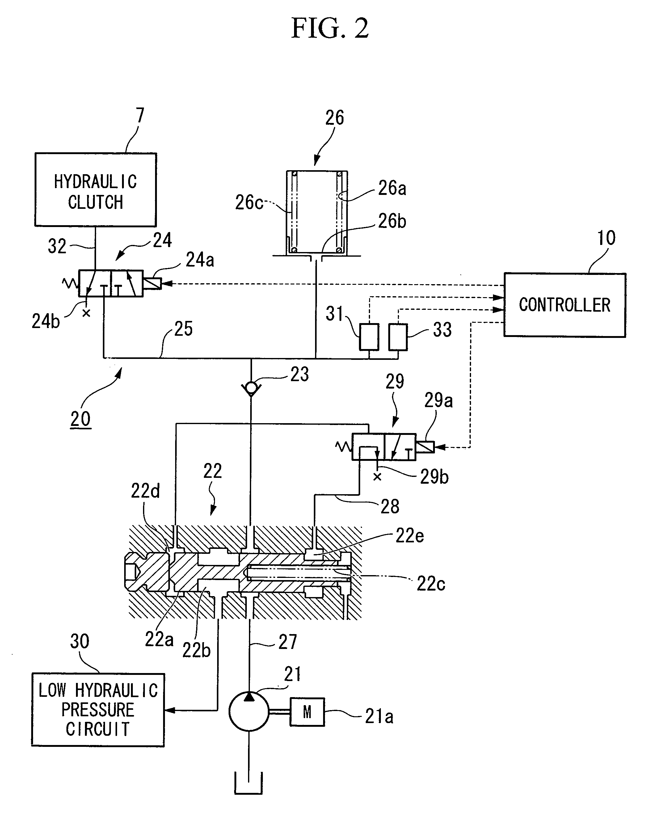
[0053] A first embodiment of the top and bottom pressure limit setting processing (i.e., PL→H and PH→L setting processing) and the regulator valve 22 switching processing are described below in accordance with the flowcharts shown in FIGS. 3 to 5.
[0054] Firstly, the top and bottom pressure limit setting processing will be described in accordance with the flowchart in FIG. 3. The top and bottom pressure limit setting processing routine shown in the flowchart in FIG. 3 is executed repeatedly at predetermined times by the controller 10.
[0055] Firstly, in step S101, whether or not the hydraulic clutch 7 is ON is determined. In the present embodiment, it is determined that the hydraulic clutch 7 is ON when the solenoid 24a of the clutch control valve 24 is being energized.
[0056] If the result of the determination in step S101 is YES (i.e., if the hydraulic clutch 7 is ON), the routine moves to step S102 and the shift range of the vehicle 1 is read. The routine then advances to step S1...
second embodiment
[0092] The technological basis of the above described first embodiment is the fact that the transmission torque capacity of the hydraulic clutch 7 depends mainly on the supply hydraulic pressure, and the bottom pressure limit PL→H, which is the threshold value at which the electric oil pump 21 is switched from a low-pressure mode to a high-pressure mode, is altered in accordance with the vehicle speed. Consequently, fundamentally, although it is possible to secure the required transmission capacity during an engagement of the hydraulic clutch 7, if this is analyzed in detail, the transmission torque capacity of the hydraulic clutch 7 changes slightly depending on the fluid temperature of the supply fluid. Because there is a reduction in viscosity as the fluid temperature rises, there is a reduction in the transmission torque capacity.
[0093] Therefore, in the present second embodiment, it is possible to set a more accurate bottom limit pressure PL→H by correcting the bottom pressure...
third embodiment
[0102] Next, a third embodiment of the top and bottom pressure limit setting processing (i.e., PL→H, PH→L setting processing) and the switching processing for the regulator valve 22 will be described.
[0103] Note that the switching processing for the regulator valve 22 in the third embodiment is the same as in the first embodiment. Therefore, the flowcharts in FIGS. 4 and 5 may be invoked and a description thereof here is omitted. Note also that, in the present third embodiment as well, a pressure increase control device and a pressure increase stopping control device are realized as a result of the controller 10 executing the processing sequence of steps S201 to S217.
[0104] The difference between the third embodiment and the first embodiment is the top and bottom pressure limit setting processing executed in step S202 of the switching processing. The top and bottom pressure limit setting processing of the third embodiment will now be described in accordance with the flowchart show...
PUM
 Abstract
Description
Claims
Application Information
 - R&D
- Intellectual Property
- Life Sciences
- Materials
- Tech Scout
- Unparalleled Data Quality
- Higher Quality Content
- 60% Fewer Hallucinations
Browse by: Latest US Patents, China's latest patents, Technical Efficacy Thesaurus, Application Domain, Technology Topic, Popular Technical Reports.
© 2025 PatSnap. All rights reserved.Legal|Privacy policy|Modern Slavery Act Transparency Statement|Sitemap|About US| Contact US: help@patsnap.com


