Optical pickup device and information recording/reproducing apparatus

a technology of optical pickup and information recording, which is applied in the direction of optical recording heads, data recording, instruments, etc., can solve the problems of increasing assembly work man hours, and increasing the size and cost of optical pickup devices, so as to enhance the performance of optical pickup devices and reduce the number of output terminals. , the effect of accurate rotation adjustmen

Inactive Publication Date: 2007-04-12
SHARP KK
View PDF0 Cites 7 Cited by
  • Summary
  • Abstract
  • Description
  • Claims
  • Application Information

AI Technical Summary

Benefits of technology

[0092] By adjusting the main-beam to the central position of the main-beam light receiving area and thereafter, switching the sub-beam light receiving areas to the outputs of the relative-connections, the rotation error and the pitch error of the sub-beams can be detected twice as sensitive as those detected by the method in which the one sides of the in-phase connections are open. Thus, an accurate rotation-adjustment and pitch adjustment can be performed, thereby being able to enhance the performance of the optical pickup device. Furthermore, by switching to the in-phase connection outputs after the rotation-adjustment and the pitch adjustment are performed, the number of output terminals can be reduced, thereby being able to miniaturize the optical pickup device.
[0093] Furthermore, by movement-adjusting, performed by a structure capable of movement-adjustment, the grating section in the direction of the optical axis, whereby the grating section is provided in order to form the sub-beams which are used for detecting the tracking error, the pitch error of the sub-beams which are incident on the light receiving element can be adjusted, thereby being able to enhance the performance of the optical pickup device.
[0094] As described above, according to the present invention, in the optical pickup device capable of handling two wavelengths, two types of lights (e.g., laser lights) having different wavelengths from each other are incident on the first PBS, which is arranged farther from the optical recording medium, from different directions from each other, both of them, for example, as P polarized lights. In accordance with each of the wavelengths emitted from light sources (e.g., semiconductor laser elements), one of them is transmitted through the inclined plane (mirror plane) of the first PBS and the other is reflected on the inclined plane of the first PBS and then combined into the same optical path. The P polarized light emitted from the first PBS is transmitted through the inclined plane of the second PBS, which is arranged closer to the optical recording medium, and irradiated onto the optical recording medium. The polarization component which is a return light from the optical recording medium is reflected on the mirror plane of the second PBS and guided to the light receiving element. As a result, a ½ wavelength plate which is conventionally required in order to cause the laser lights to be incident on the two PBSs is not needed, thereby being able to miniaturize and reduce the cost of the optical pickup device. Furthermore, by reflecting the polarization component, which is reflected by the optical recording medium, on the second PBS arranged before the semiconductor laser elements as light sources and guiding the polarization component to the light receiving element, the amount of return light to the semiconductor laser elements is reduced and the noise occurrence is suppressed, thereby being able to enhance the reliability of the optical pickup device. Furthermore, by attaching the ¼ wavelength plate to the second PBS, it is possible to miniaturize the optical pickup device.
[0095] Furthermore, by increasing the freedom of arranging the light receiving element for power control, the freedom of designing the PBSs is increased, thereby being able to reduce the cost of the PBSs. Furthermore, by rotation-adjusting the cylindrical lens with the optical axis as its center, a stable tracking error signal and focus error signal can be produced, thereby being able to enhance the reliability of the optical pickup device. Furthermore, by switching between the outputs of the in-phase connections and the outputs of the relative-phase connections in the four-divided sub-beam light receiving areas for detecting the tracking error by using the switching section, it is possible to enhance the adjustment accuracy for the sub-beam position without increasing the number of output terminals. Furthermore, by movement-adjusting the grating section, which is used for generating sub-beams for detecting the tracking error, in the direction of the optical axis, it is possible to adjust the pitch error of the sub-beams.
[0096] According to another embodiment of the present invention, in the optical pickup device capable of handing two wavelengths, a second laser light of two types of laser lights is incident as an S polarized light on the first PBS, which is arranged farther from the optical recording medium, reflected on the inclined plane of the first PBS, then transmitted through the inclined plane of the second PBS, which is arranged closer to the optical recording medium and irradiated onto the optical recording medium. A first laser light of two types of the laser lights is incident as an S polarized light on the second PBS, reflected on the inclined plane of the second PBS and irradiated onto the optical recording medium. The polarization component, which is a reflection light reflected from the optical recording medium is reflected on the inclined plane of the second PBS and then guided to the light receiving element. As a result, a ½ wavelength plate which is conventionally required in order to cause the laser lights to be incident on the two PBSs is not needed, thereby being able to miniaturize and reduce the cost of the optical pickup device. Furthermore, since a raise mirror is not used, it is possible to miniaturize the optical pickup device. Furthermore, by constructing the first PBS with a flat-plate, it is possible to miniaturize and reduce the cost of the optical pickup device. Furthermore, by attaching the ¼ wavelength plate to the second PBS, it is possible to miniaturize the optical pickup device. Furthermore, by integrating the second PBS, the light receiving element for power control and the ¼ wavelength plate together and placing a portion thereof in the drum of the actuator for driving the objective lens, it is possible to miniaturize the optical pickup device.
[0097] Furthermore, by increasing the freedom of arranging the light receiving element for power control, the freedom of designing the PBSs is increased, thereby being able to reduce the cost of the PBSs. Furthermore, by rotation-adjusting the cylindrical lens with the optical axis as its center, a stable tracking error signal and focus error signal can be produced, thereby being able to enhance the reliability of the optical pickup device. Furthermore, by switching between the outputs of the in-phase connections and the outputs of the relative-phase connections in the four-divided sub-beam light receiving areas for detecting the tracking error by using the switch section, it is possible to enhance the adjustment accuracy for the sub-beam position without increasing the number of output terminals. Furthermore, by movement-adjusting the grating section, which is used for generating sub-beams for detecting the tracking error, in the direction of the optical axis, it is possible to adjust the pitch error of the sub-beams.

Problems solved by technology

However, the use of the ½ wavelength plates 15 and 17 arises a problem of increasing the size and cost of the optical pickup device.
As a result, the use of many parts in an optical pickup device leads to the cost increase of the device and the man hour increase for assembly work as well as leading to increasing the size of the device.
As described above, there is a problem that the conventional pickup device capable of handling two wavelengths cannot meet the request from the market in view of the cost and assembly of the device.
Thus, it is becoming difficult to secure the playability of the optical pickup device.

Method used


Image

  • Optical pickup device and information recording/reproducing apparatus
  • Optical pickup device and information recording/reproducing apparatus
  • Optical pickup device and information recording/reproducing apparatus

Examples


embodiment 1

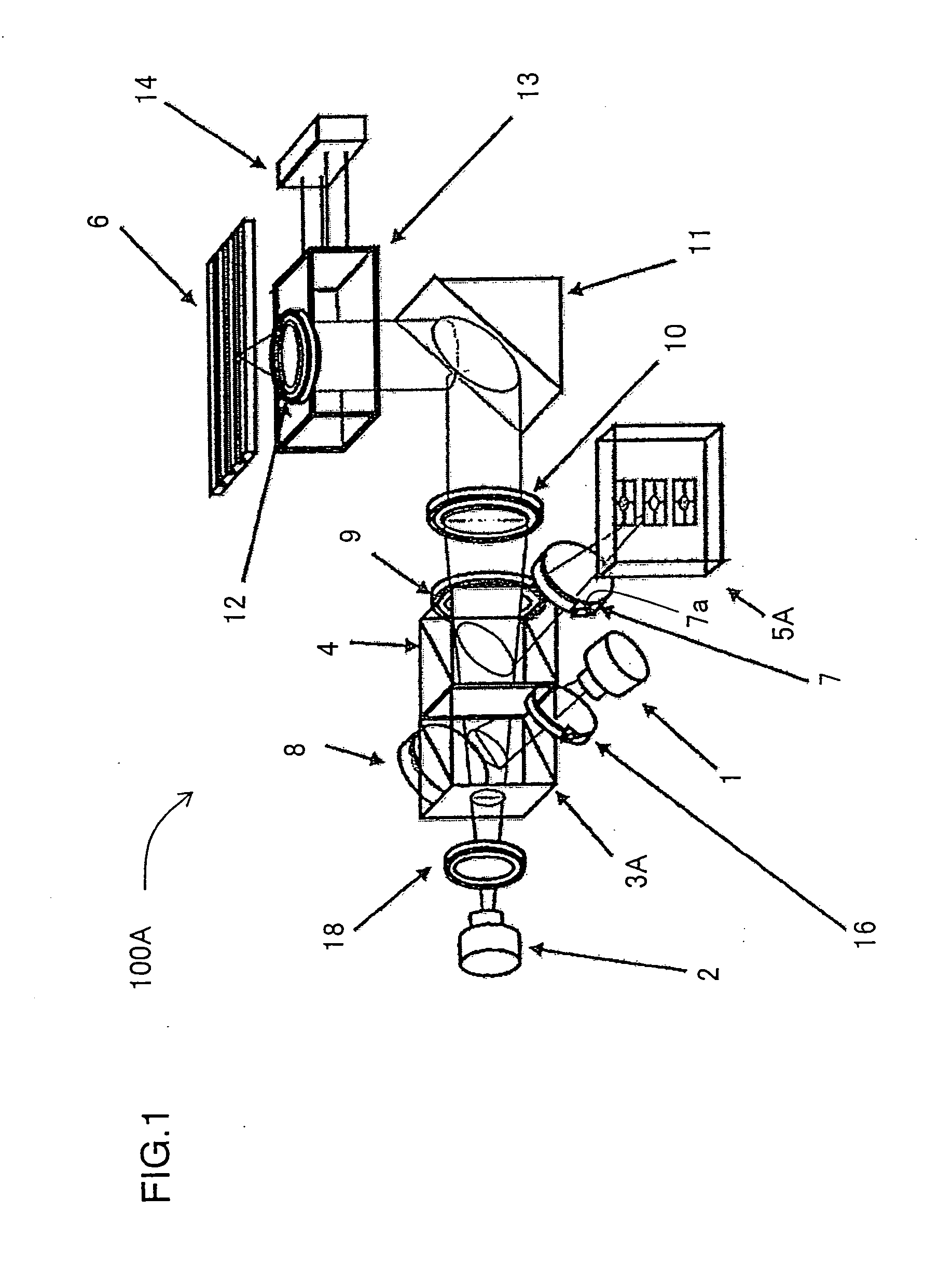
[0116]FIG. 1 is a perspective view showing a structural example of important parts of an optical pickup device capable of handling two wavelengths according to Embodiment 1 of the present invention.

[0117] In FIG. 1, the optical pickup device 100A capable of handling two wavelengths includes a semiconductor laser element 1 for DVD which has a relatively short-wavelength, a semiconductor laser element 2 for CD which has a relatively long-wavelength, a cube-type first PBS 3A arranged farther from an optical disk 6, a cube-type second PBS 4 arranged closer from the optical disk 6 and a light receiving element 5A for receiving a reflection light reflected from the optical disk 6.

[0118] Laser lights from the semiconductor laser elements 1 and 2 are incident on the first PBS 3A, both of them as P polarized lights, from different directions from each other. The laser light from the semiconductor laser element 1 having a short-wavelength is reflected on the inclined plane (mirror plane) of...

embodiment 2

[0158]FIG. 6 is a perspective view showing a structural example of important parts of an optical pickup device capable of handling two wavelengths according to Embodiment 2 of the present invention.

[0159] In FIG. 6, the optical pickup device 100C capable of handling two wavelengths includes semiconductor laser elements 1 and 2 having different wavelengths from each other, a first PBS 3B arranged farther from an optical disk 6, a second PBS 4 arranged closer from the optical disk 6 and a light receiving element 5A for receiving a reflection light reflected from the optical disk 6. The second PBS 4 is a cube-type polarization beam splitter. As the first PBS 3B, either a cube-type polarization beam splitter or a flat-plate-type polarization beam splitter can be used. In Embodiment 2, the flat-plate-type polarization beam splitter is used as the first PBS 3B.

[0160] A laser light emitted from the semiconductor laser element 1 is incident on the second PBS 4 as an S polarized light and ...


PUM

PropertyMeasurementUnit
wavelengthsaaaaaaaaaa
¼ wavelengthaaaaaaaaaa
in-phase positional relationshipaaaaaaaaaa

Abstract

An optical pickup device according to the present invention having two light sources is capable of emitting lights having different wavelengths from each other for recording/reproducing information on/from an optical recording medium by using a light from the light source; wherein the two light sources both are capable of emitting either polarization lights in one polarization direction or polarization lights perpendicular to the one polarization direction, and each of the two light sources is arranged at a predetermined position depending on a polarization direction of the light to be emitted.

Description

[0001] This Nonprovisional application claims priority under 35 U.S.C. §119(a) on Patent Application No.2005-296925 filed in Japan on Oct. 11, 2005, the entire contents of which are hereby incorporated by reference. BACKGROUND OF THE INVENTION [0002] 1. Field of the Invention [0003] The present invention relates to: an optical pickup device used to optically record / reproduce information on / from a disk-shaped optical recording medium (hereinafter, referred to as “optical disk”); and an information recording / reproducing apparatus using the optical pickup device. [0004] 2. Description of the Related Art [0005] In the optical pickup device of this kind, as an optical pickup device which is capable of handling a plurality of wavelengths, the following elements are provided; (i) a plurality (two or more) of semiconductor laser elements having different light source wavelengths from each other and (ii) a light receiving element for receiving a reflection light reflected from an optical dis...

Claims


Application Information

Patent Timeline
Patent Type & Authority Applications(United States)
IPC IPC(8): G11B7/135
CPCG11B7/1275G11B7/1356G11B2007/0006
Inventor YOKOTA, TAIZOH
Owner SHARP KK
Why Eureka
Try Eureka