
Multi-purpose bone plate system

a multi-purpose, bone plate technology, applied in the direction of osteosynthesis devices, prostheses, surgical staples, etc., can solve the problems of not fully supporting the three-dimensional bone segments, the bone plate disclosed by the '458 patent is clearly not suitable for multiple purposes, and the overall plate bends, so as to achieve high reliability in operation, the effect of mobility of the operated animal

Active Publication Date: 2007-04-12
SIDEBOTHAM CHRISTOPHER G
View PDF17 Cites 31 Cited by
  • Summary
  • Abstract
  • Description
  • Claims
  • Application Information

AI Technical Summary

Benefits of technology

[0018] The present invention provides a method and means for three dimensionally bending bone plates to provide three-dimensional support to fractured bone segments, thereby retaining the surgeon-set position of the bones during the bone-healing period. Shaped bone plates provided in accordance with the present invention are especially suited for canine use. Such bone plates can accommodate the small size of canine bone segments. They can be implanted so that the mobility of the operated animal is maintained immediately after surgery. Advantageously, the bone plate system of this invention provides intimate contact between fractured bone segments during the healing period. A long-term permanent bond between the implant and the underlying bone structure is effected, and extended motion meeting the canine needs is achieved. Once implanted, the bone plate is not removed during the remaining lifetime of the dog. It is highly reliable in operation, and functions continuously in the implanted condition without corrosion or rejection reactions throughout its service life.
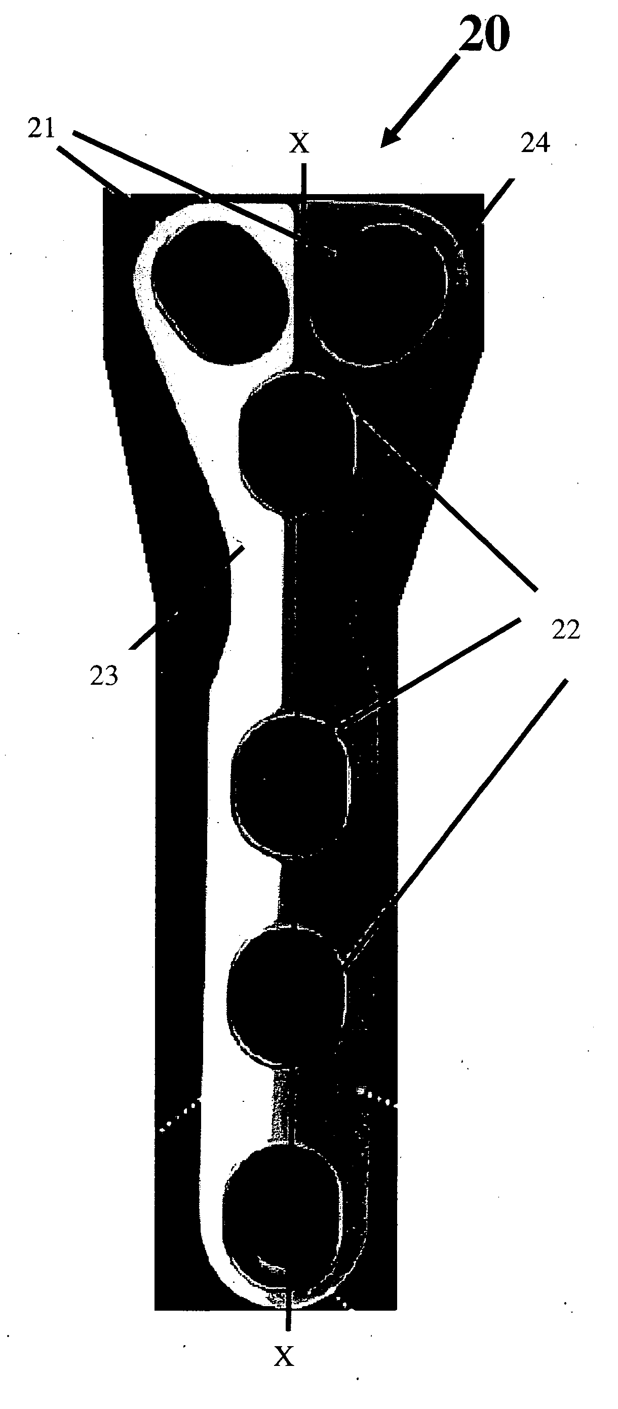
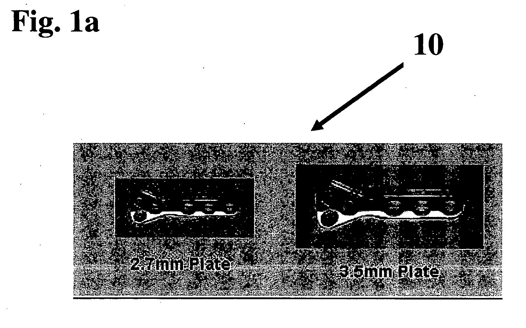
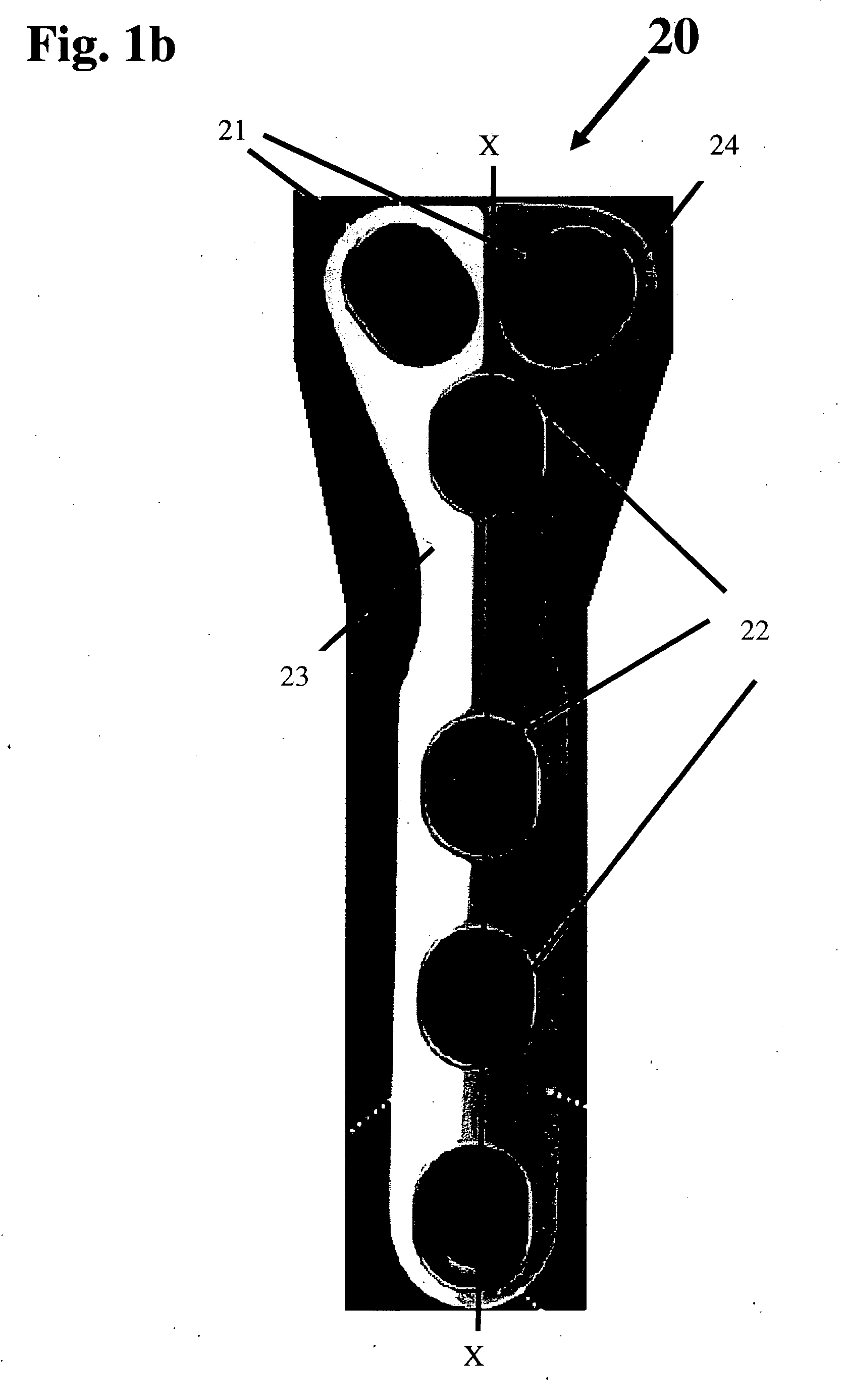
[0020] The System includes bone plates having a thickness of 2.7 mm and 3.5 mm with multiple compression and angulation slots for easy bending of the bone plate. The thicker plate is used for larger and heavier animals. The bone plate is three-dimensionally contoured in an easy to use bending and contouring tower and addresses the clinical needs of animals with various bone geometry using a single bone plate. Due to the symmetrical shape of the one plate, the bone plate may be used for the left or right side fractured bones. The multiple applications of the system include, but are not limited to, pelvic osteotomy, ilial shaft fracture, proximal tibial osteotomy, distal radial fracture and partial carpal athrodesis. The versatility of the system minimizes the need to inventory a wide selection of plates and pins in order to address the varied requirements of clinical cases.
[0021] The bone plate of the system is symmetrical, has a combination of angulation and compression slots, and can be bent into either left or right components. The multipurpose bone plate is manufactured from 316 LVM stainless steel—a standard material for surgical implants, which provides a high degree of effectiveness, as evidenced by its clinical history and laboratory testing data. Deviations from this standard can impact product strength, biocompatibility and corrosion resistance.

Problems solved by technology

It does not completely support the three dimensional bone segments that have fractured; but relies on the nails to prevent movement of the bone plate.
The bone plate disclosed by the '458 patent is clearly not suitable for multiple purposes.
The bending action only bends the overall plate and portions of the plate cannot be contoured to fit a three-dimensional fractured bone.
There is no template provided to adjust bending and twisting in accordance with surgical requirements.
It is not symmetrical, and cannot be interchangeably used for the left side and right side before bending.
The bone plate is made of solid metal and cannot be easily bent into three-dimensional shapes.
The bone plate disclosed by the '047 patent is not bendable, and cannot be easily shaped to conform to the three dimensionality of a fractured bone.

Method used


Image

  • Multi-purpose bone plate system
  • Multi-purpose bone plate system
  • Multi-purpose bone plate system

Examples


Embodiment Construction

[0029] The present invention provides a method and means bending bone plates in three dimensions to provide multi-dimensional support to fractured bone segments. Such multi-dimensional support facilitates retention of the surgeon-set position of the bones during the bone-healing period. Shaped bone plates provided in accordance with the present invention are especially suited for canine use. Such bone plates can accommodate the small size of canine bone segments. They can be implanted so that the mobility of the operated animal is maintained immediately after surgery. An intimate contact between fractured bone segments is provided during the healing period. A long-term, permanent bond between the implant and the underlying bone structure is achieved. This long-term, permanent bond affords extended motion, thereby meeting canine needs. Once implanted, the bone plate is not removed during the remaining lifetime of the dog. It is highly reliable in operation, and functions continuously...


PUM


Abstract

A multi-purpose bone plate system comprises a set of sterile malleable bone plates, an adjustable bending and contouring tower with adjustable angulation and compression slots and a set of bone plates with angulation and compression slots positioned at pre-selected locations to aid three-dimensional shaping of the bone plate. The surgeon inserts the sterile bone plate template to surround the fractured bone and works the template to acquire the physical shape of the fractured bone, inserts the template into the tower to set the adjustable angulation and compression slots of the tower. Now a symmetrical bone plate is inserted into the tower and bent to a shape that replicates the shape of the bone plate. The three-dimensionally shaped bone plate is sterilized and is attached by screws or nails surrounding the fractured bone segment and provides support to fractured bone segments during healing of the bone.

Description

BACKGROUND OF THE INVENTION [0001] 1. Field of the Invention [0002] The present invention relates to a bone plate system and apparatus for bending bone plates; and more particularly, to a system that comprises readily formable bone plates and a bending and configuring tower designed to create a bone plate shape that matches a template. [0003] 2. Description of the Prior Art [0004] Many patents address issues related to bone plates and apparatus for bending bone plates. Some of the patents relate to bone plates for human use while others relate to bone plates for canine use. [0005] U.S. Pat. No. 2,737,835 to Herz discloses tools for bonding plates in bone surgery. A flat plate is bent at a suitable location using a bending tool. As shown above in FIG. 4, three Smith-Petersen nails are inserted in one of the broken femur bones and a fourth nail is inserted into the femoral shaft to rigidly hold the broken bones in place without movement, to promote bone healing. The plate used is a tw...

Claims


Application Information

Patent Timeline
IPC IPC(8): A61F2/30
CPCA61B17/8085A61B17/8863
Inventor SIDEBOTHAM, CHRISTOPHER G.
Owner SIDEBOTHAM CHRISTOPHER G
Learn More