
System and method for determining a NOx storage capacity of catalytic device

Active Publication Date: 2007-04-19
FORD GLOBAL TECH LLC
View PDF2 Cites 14 Cited by
  • Summary
  • Abstract
  • Description
  • Claims
  • Application Information

AI Technical Summary

Benefits of technology

[0002] Lean-burning engines, or engines that run on an air / fuel mixture with a stoichiometrically greater amount of air than fuel, can offer improved fuel economy relative to engines configured to run on stoichiometric air / fuel mixtures.
[0003] However, lean-burning engines also may pose various disadvantages. For example, burning a lean air / fuel mixture may decrease the reduction of nitrogen oxides (collectively referred to as “NOx”).
[0004] Various mechanisms have therefore been developed to reduce NOx emissions in lean-burning engines. One mechanism is a catalyst known as a lean NOx trap. The NOx trap is a catalytic device typically positioned downstream of the catalytic converter in an emissions system, and is configured to retain NOx when the engine is producing a lean exhaust for eventual reduction when the engine produces a rich exhaust. A typical NOx trap includes an alkaline-earth metal, such as barium, and / or an alkali metal, such as potassium, to which NOx adsorbs when the engine is running a lean air / fuel mixture. The engine can then be configured to produce a rich exhaust containing carbon monoxide, hydrogen gas and various hydrocarbons to reduce the NOx in the trap, thus decreasing NOx emissions and purging the trap.
[0005] Various methods may be used to determine when a NOx trap needs to be purged. For example, a NOx sensor may be used to measure NOx emissions behind a NOx trap during lean engine operation. With an estimate of the feedgas NOx concentration (which is the NOx contained in exhaust from the engine), the NOx storage efficiency of the trap can be calculated. This may be used to determine when the storage efficiency of the trap has dropped below a minimum threshold value, and therefore when the trap needs to be purged. However, NOx sensors typically are expensive, and can significantly increase the cost of the lean aftertreatment system.
[0006] The inventors herein have realized that a NOx storage capacity of a catalytic device such as a NOx trap may be efficiently and accurately estimated from outputs of exhaust oxygen sensors positioned upstream and downstream of the catalytic device by utilizing a method of operating an engine, wherein one embodiment of the method includes operating the engine at a rich air / fuel ratio for a first interval; adjusting a temperature of the catalytic device to a diagnostic temperature for measuring an oxygen uptake by the catalytic device; operating the engine at a lean air / fuel ratio for a second interval; and adjusting the temperature of the catalytic device to an operating temperature. An oxygen storage capacity of the catalytic device may be measured while at the diagnostic temperature from a difference between the signals from the upstream and downstream oxygen sensors, and a NOx storage capacity of the catalytic device may be determined from the measured oxygen storage capacity. By performing the diagnostic in the diagnostic temperature range, a more repeatable and robust OSC measurement can be made.

Problems solved by technology

However, lean-burning engines also may pose various disadvantages.
However, NOx sensors typically are expensive, and can significantly increase the cost of the lean aftertreatment system.

Method used


Image

  • System and method for determining a NOx storage capacity of catalytic device
  • System and method for determining a NOx storage capacity of catalytic device
  • System and method for determining a NOx storage capacity of catalytic device

Examples


Embodiment Construction

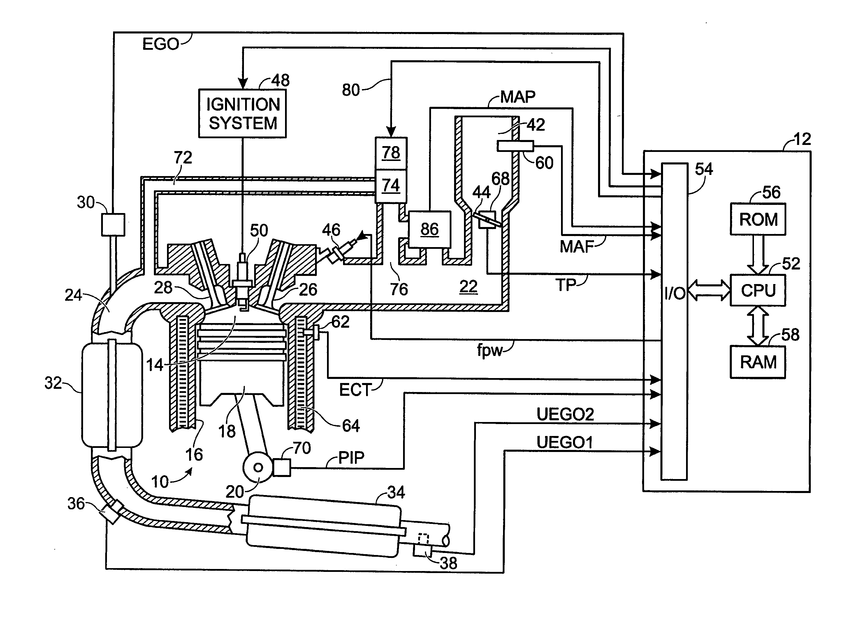
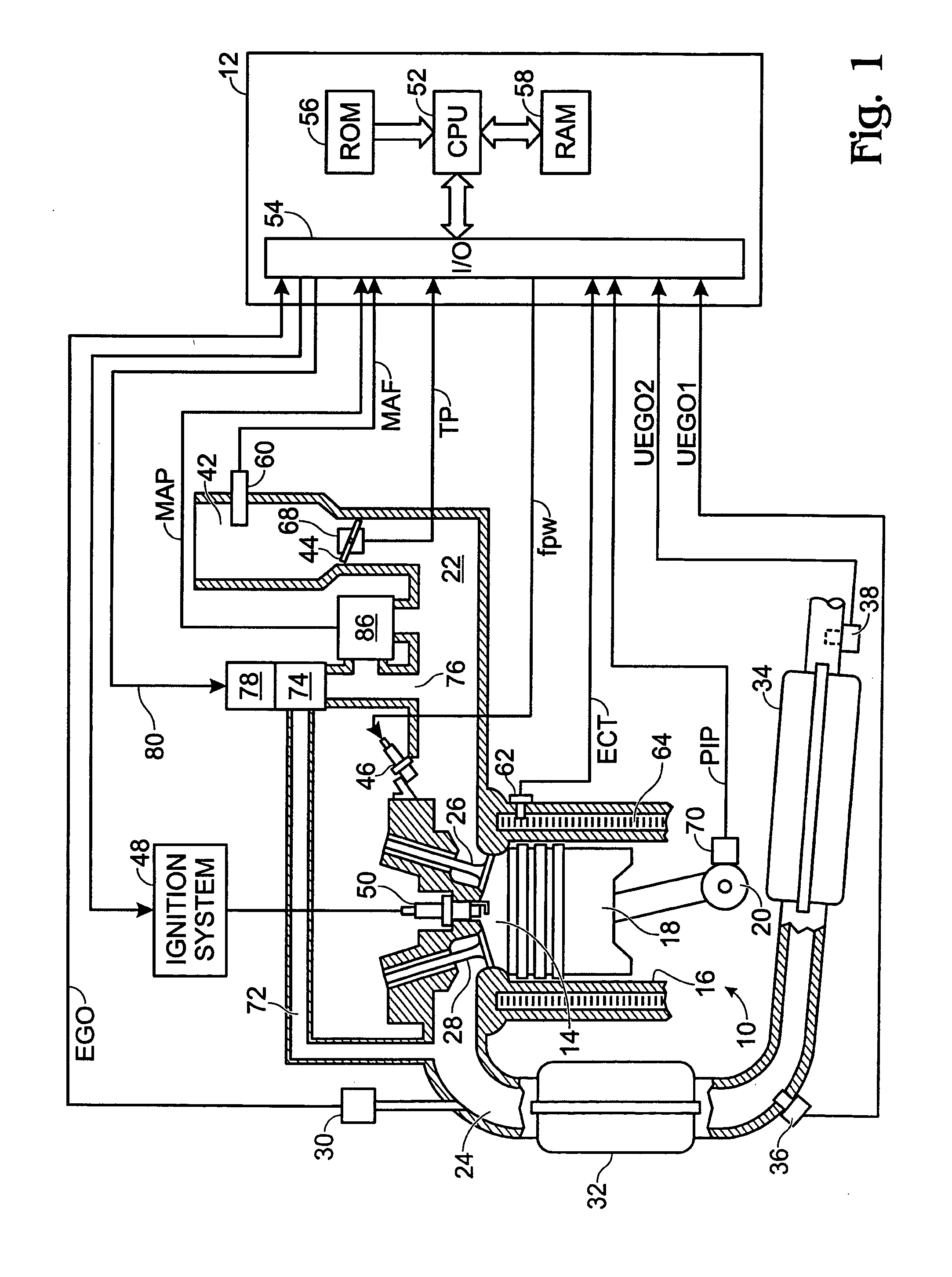
[0022]FIG. 1 shows a schematic depiction of an internal combustion engine 10. Engine 10 typically includes a plurality of cylinders, one of which is shown in FIG. 1, and is controlled by an electronic engine controller 12. Engine 10 includes a combustion chamber 14 and cylinder walls 16 with a piston 18 positioned therein and connected to a crankshaft 20. Combustion chamber 14 communicates with an intake manifold 22 and an exhaust manifold 24 via a respective intake valve 26 and exhaust valve 28. An exhaust gas oxygen sensor 30 is coupled to exhaust manifold 24 of engine 10. A three-way catalyst 32 is connected to and receives feedgas from exhaust manifold 24, and a NOx trap 34 is connected to and receives emissions from three-way catalyst 32. Furthermore, a first UEGO sensor 36 is positioned between three-way catalyst 32 and NOx trap 34, and a second UEGO sensor 38 is positioned downstream of NOx trap 34. Engine 10 is depicted as a port-injection spark-ignition gasoline engine. How...


PUM


Abstract

In an apparatus having an internal combustion engine, a catalytic device for treating emissions from the engine, an upstream oxygen sensor positioned upstream of the catalytic device, a downstream oxygen sensor positioned downstream of the catalytic device, and a controller configured to determine a NOx storage capacity of the catalytic device from a difference between a signal received from the upstream oxygen sensor and a signal received from the downstream oxygen sensor, a method of operating the engine is disclosed, the method including operating the engine at a rich air / fuel ratio for a first interval; adjusting a temperature of the catalytic device to a diagnostic temperature for measuring an oxygen uptake by the catalytic device; operating the engine at a lean air / fuel ratio for a second interval; and adjusting the temperature of the catalytic device to an operating temperature.

Description

TECHNICAL FIELD [0001] The present application relates to the field of automotive emission control systems and methods. BACKGROUND AND SUMMARY [0002] Lean-burning engines, or engines that run on an air / fuel mixture with a stoichiometrically greater amount of air than fuel, can offer improved fuel economy relative to engines configured to run on stoichiometric air / fuel mixtures. [0003] However, lean-burning engines also may pose various disadvantages. For example, burning a lean air / fuel mixture may decrease the reduction of nitrogen oxides (collectively referred to as “NOx”). [0004] Various mechanisms have therefore been developed to reduce NOx emissions in lean-burning engines. One mechanism is a catalyst known as a lean NOx trap. The NOx trap is a catalytic device typically positioned downstream of the catalytic converter in an emissions system, and is configured to retain NOx when the engine is producing a lean exhaust for eventual reduction when the engine produces a rich exhaus...

Claims


Application Information

Patent Timeline
IPC IPC(8): F01N3/00
CPCF01N3/0807F01N3/0842F01N3/106F01N11/007F01N2560/025F01N2560/14F02D41/0275F02D41/1441F02D41/1475F02D2200/0802F02D2200/0808F02D2200/0816Y02T10/47F01N13/009Y02T10/40
Inventor SURNILLA, GOPICHANDRAGORALSKI, CHRISTIAN T. JR.PATTERSON, JOSEPH E.THEIS, JOSEPH R.ELWART, SHANE
Owner FORD GLOBAL TECH LLC
Learn More