
Shock absorbing dental device

Inactive Publication Date: 2007-04-19
NAPOLI SALVATORE +2
View PDF35 Cites 40 Cited by
  • Summary
  • Abstract
  • Description
  • Claims
  • Application Information

AI Technical Summary

Benefits of technology

[0009] In accordance with one aspect of the present invention, the dental device constructed in the nature of a mouthguard diminishes the total force imparted to the teeth and associated structures by a potentially damaging blow, in addition to distributing the force over a greater time and a larger surface area. The attenuation of the total force is effected by the application, in one or more of several embodiments, of an open cell structure containing a fluid material. The open cell structure is designed as a shock absorbing functional unit hereinafter called an Impact Attenuation Component or IAC that may be an integral nondetachable part of the mouthguard or a separate detachable and replaceable unit that is affixed into the mouthguard.
[0010] The IAC of the mouthguard provides mechanical protection properties and optionally controls secondary damage to teeth engendered by the use of mouthguards. The principles employed by the IAC as to mechanical protection provides the mouthguard with a crumple zone wherein a specific region or regions of the IAC are deformed or permanently crumpled in order to absorb as much of the potentially damaging impact of a collision as possible. In this way, less of the total kinetic energy of the collision impact is transferred to the teeth or other associated structures.
[0011] The energy that is absorbed in the deformation or crumpling of the IAC is not stored as elastic energy, but is dissipated as kinetic energy in the movement of the fluid material, heat, sound and other entropy increasing mechanisms with the deformation or crumpling of the crumple zone of the IAC. The main function of the dental device is to limit the damage to and within the IAC of the mouthguard to the greatest degree possible, and thereby reduce injury to teeth and associated structures and brain.
[0018] In accordance with another embodiment of the dental device, proactively protective elements are incorporated in the design of the IAC. Although protection of the oral soft tissues and dentoalveolar structures is the primary purpose of this dental device, consideration is also given to the secondary damage caused or facilitated by mouthguards. In one embodiment of the design of the IAC, the skeletal superstructure has an open-cell design. The semi-solid or gel-like contents of the cells or compartments may contain chemical agents held in suspension or solution. These agents may be active or inactive substances. During the time that the protective mouthguard is employed, these agents elute into the saliva and fluids coating the teeth and associated structures. The incorporation of hydrophilic materials into the fluid materials used in the mouthguard that are neutral or beneficial to the denition, e.g., agents such as xylitol, is a significant advantage in protecting the teeth from the increased cariogenic environment found when mouthguards are use in athletic activities.
[0024] In accordance with one embodiment of the present invention, there is described a method for protecting the teeth of a user from an impact, the method comprising positioning an arch of teeth within a channel formed in a carrier, the carrier including an outer wall having at least one insert therein, the insert comprising a shock absorbing body adapted to be rendered impermeable upon application of a sufficient force thereto, and replacing the insert with another one of the inserts when the insert is rendered inoperable upon application of a sufficient force thereto.

Problems solved by technology

Injury to the teeth and associated structures is a serious risk in many sports and athletic activities.
This places a limit on the protectiveness of conventional mouthguards in that the total force is still imparted to the teeth and associated structures.
This results in other concerns that have not been addressed by known mouthguards.
It is common knowledge that when these athletes engage in strenuous physical activity, they lose and must replace significant amounts of fluids, nutrients and calories.
Whatever the cause, reduced salivary flow greatly increases the incidence of dental caries and periodontal disease.
Regarding physical protection, stock mouthguards are typically the cheapest and least effective in use while the custom molded and shaped mouthguards are the most expensive and effective in their impact absorbent properties.

Method used


Image

  • Shock absorbing dental device
  • Shock absorbing dental device

Examples


Embodiment Construction

[0031] In describing the preferred embodiments of the subject matter illustrated and to be described with respect to the drawings, specific terminology will be resorted to for the sake of clarity. However, the invention is not intended to be limited to the specific terms so selected, and is to be understood that each specific term includes all technical equivalence which operate in a similar manner to accomplish a similar purpose.

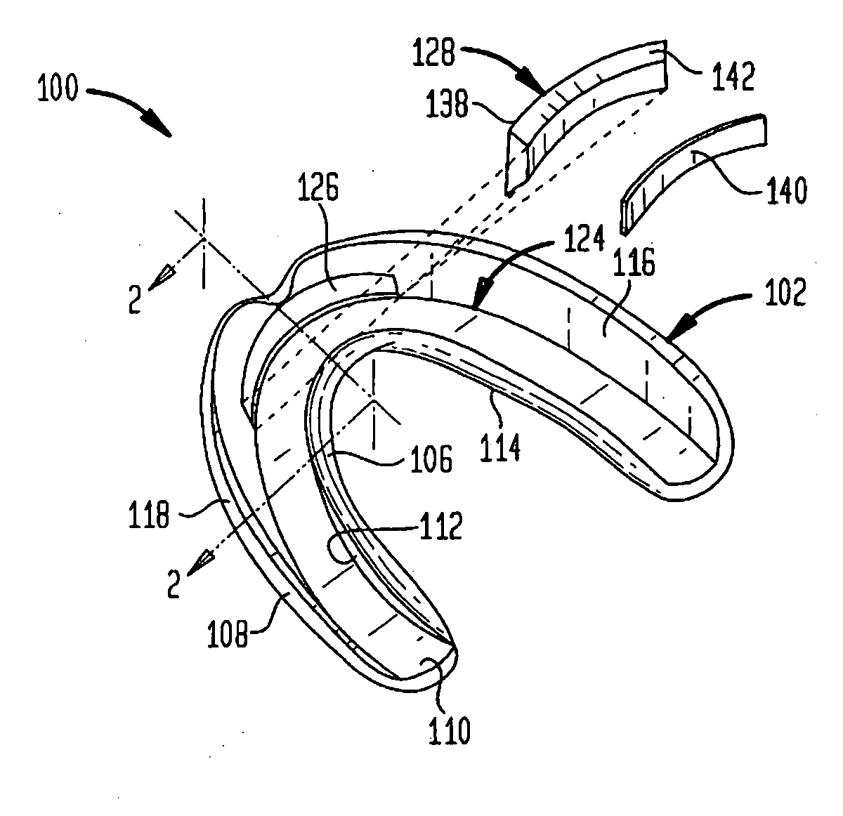
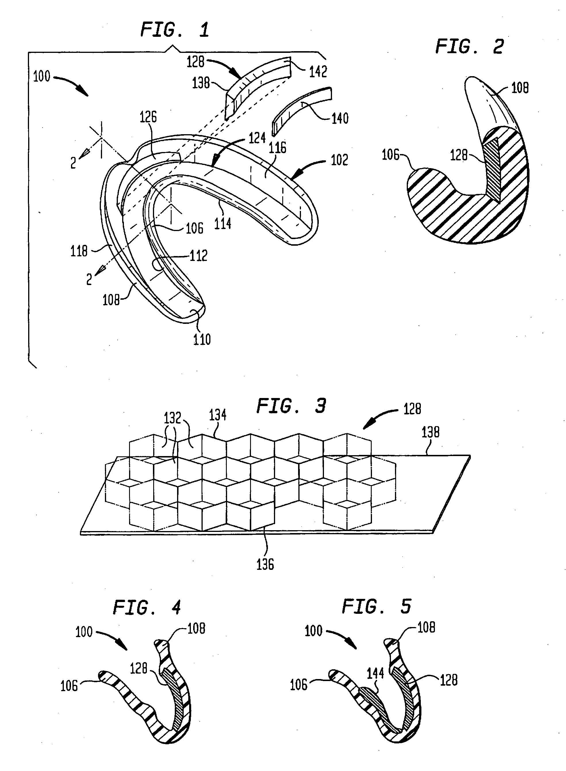
[0032] Referring to the drawings, and specifically FIGS. 1 and 2, there is illustrated a dental device having shock absorbing properties for protecting the wearer's teeth, dental arches, mandible, maxilla, temporomandibular, and lips. In addition, as to be described hereinafter, the dental device is adapted for optionally providing a beneficial agent intra-orally to the teeth in a proactive manner, for example, such as protecting the teeth from the increased cariogenic environment found when mouthguards are used, particularly during athletic activities.

[0...


PUM


Abstract

An intraoral dental device includes an insert for protecting the teeth, dental arches, mandible, maxilla, temporal mangila joint and lips of the wearer from impact that may arise in athletic activities. The insert is an open cell structure which may optionally contain a fluid material, such as hydrogels, amorphous solids, semisolids, liquids and / or gases. The insert may be permanently or resiliently deformable whereby a portion of the fluid material, if present, is expelled from the insert's cells. The inserts are replaceable after they are rendered ineffective from the sustained impact.

Description

BACKGROUND OF THE INVENTION [0001] The present invention relates to a method and dental device for protecting the teeth, dental arches, mandible, maxilla, temporomandibular joint and lips, while optionally providing a beneficial agent to the teeth, and more particularly, to an intra-oral dental device that is worn on an arch of teeth. [0002] Injury to the teeth and associated structures is a serious risk in many sports and athletic activities. Associated structures include the dental arches, upper and lower jaws (maxilla and mandible), temporomandibular joints, lips and tongue. A significant percentage of these injuries may be prevented or attenuated by the use of a mouthguard. [0003] The primary function of a mouthguard is to redistribute the force of a potentially damaging blow to the teeth and associated structures over an extended period of time and a larger surface area. In this way, the peak force necessary to break and / or damage the teeth and associated structures may not be ...

Claims


Application Information

Patent Timeline
IPC IPC(8): A61C5/14
CPCA63B71/081A63B71/085
Inventor NAPOLI, SALVATOREBARDACH, LAURAGEDULDIG, JAMES
Owner NAPOLI SALVATORE
Learn More