Induction heating apparatus

a technology of induction heating and heating chamber, which is applied in the direction of electric/magnetic/electromagnetic heating, process and machine control, etc., can solve the problems of abnormal drive signals of the control terminal of the switching element, abnormal operation defect of the induction heating cooker of the reference, etc., and achieve high reliability

Inactive Publication Date: 2007-04-19
SANKEN ELECTRIC CO LTD
View PDF10 Cites 26 Cited by
  • Summary
  • Abstract
  • Description
  • Claims
  • Application Information

AI Technical Summary

Benefits of technology

[0021] When power source (60) produces the output of low voltage level, resonance waveform detector (6) generates to phase comparator (8) a detection signal (DS1) of lowered voltage level below the operation threshold value (VTH) for phase comparator (8). However, addition circuit (13) superimposes the drive signal (D1) from drive circuit (7) on the detection signal (DS1) from resonance waveform detector (6) to prepare the superimposed signal of the level at least a part of which reaches or exceeds the operation threshold value (VTH) for phase comparator (8). Specifically, drive signals (D1, D2) are biased, amplified or adjusted to a certain high voltage level in drive circuit (7) and originally generated with a constant frequency before the modulation, and detection signals (DS1) are generated with generally constant phase difference and varied with generally same frequency relative to drive signals (D1, D2). Accordingly, even though power source (60) generates the output of lowered voltage level, at least a part of the superimposed signal of detection signal (DS1) and drive signal (D1) can be maintained on a level same as or over the operation threshold value (VTH) for phase comparator (8), while keeping normal operation of phase comparator (8). For that reason, phase comparator (8) supplies drive circuit (7) with a correct adjusting signal (PH) corresponding to phase difference between detection signal (DS1) and drive signal (D1) so that drive circuit (7) provides switching element (11, 12) with drive signals (D1, D2) with the oscillation frequency corresponding to the level of adjusting signal (PH) from phase comparator (8). Consequently, even though control circuit (5) rapidly responds to change in load, the apparatus can prevent rapid change in oscillation frequency of drive circuit (7) to stably and reliably turn switching element (11, 12) in inverter circuit (3) on and off.
[0022] The present invention can provide a highly reliable induction heating apparatus that can correctly turn a switching element in inverter circuit on and off.

Problems solved by technology

Induction heating cooker of the reference, however, has a defect of performing abnormal operation.
Specifically, while a control circuit promptly responds to existence or absence of or alteration in a heated object, self-excitation oscillator oscillates with the natural frequency, and when the natural frequency by self-excitation oscillator is rapidly and increasingly deviated from oscillation frequency by self-excitation oscillator driven by trigger pulses of comparator, drive circuit may disadvantageously supply control terminal of switching element with abnormal drive signals.

Method used


Image

  • Induction heating apparatus
  • Induction heating apparatus
  • Induction heating apparatus

Examples


Embodiment Construction

[0032] Embodiments of the induction heating apparatus according to the present invention will be described hereinafter in connection with FIGS. 1 to 5 of the drawings. Same reference symbols as those shown in FIGS. 6 to 8 are applied to similar portions in these drawings, omitting explanation therefor.

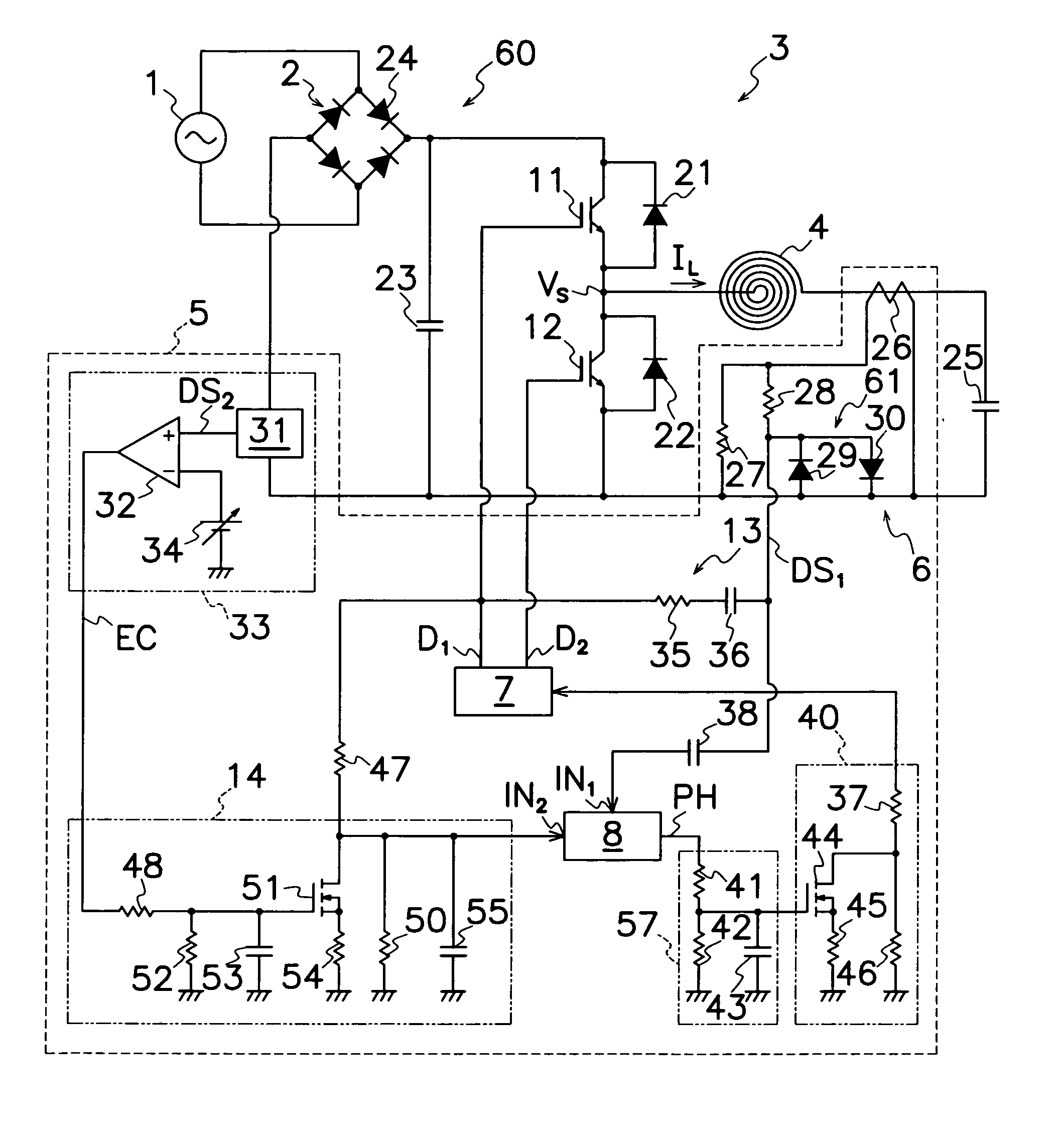
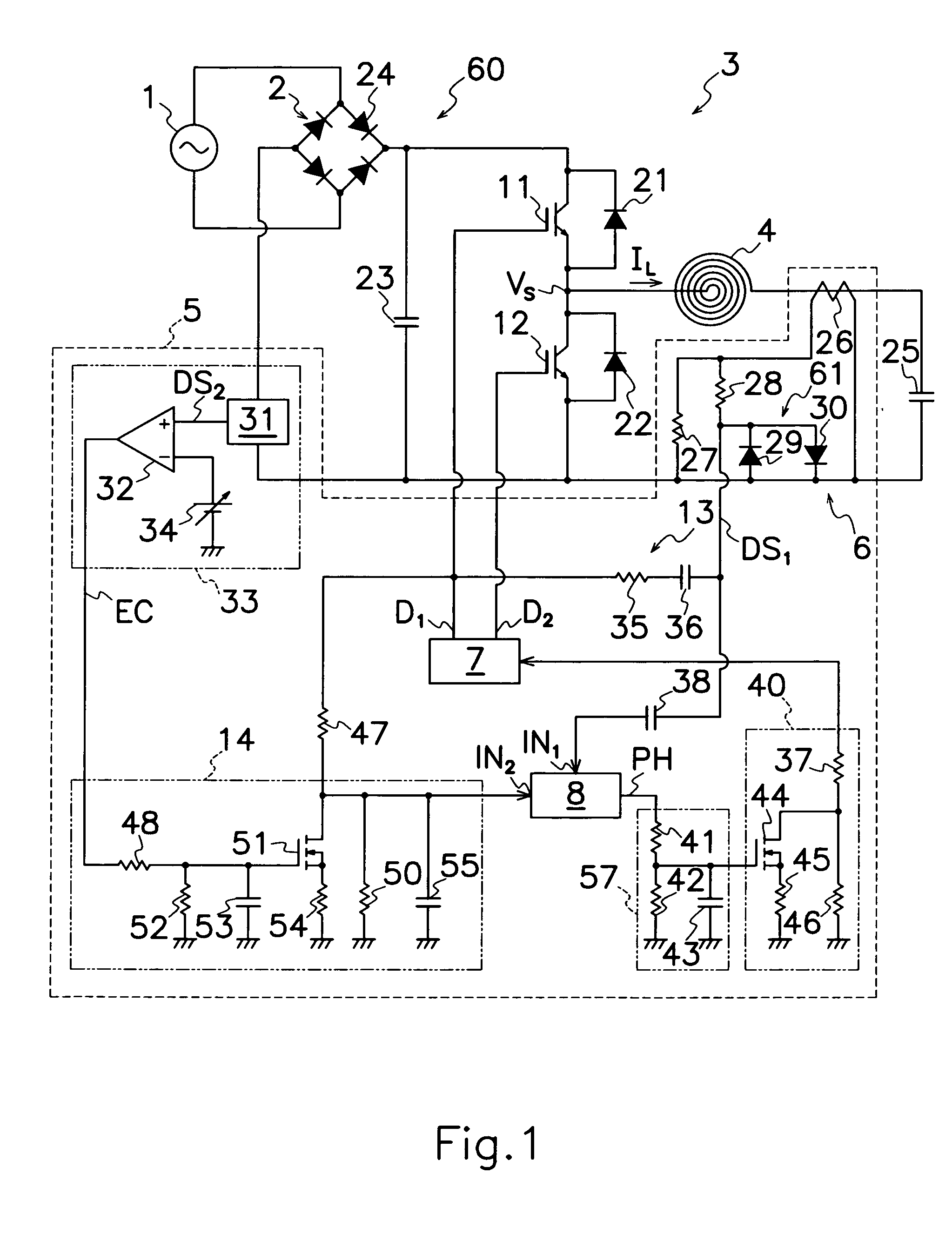
[0033] Unlike the prior art induction heating apparatus shown in FIG. 5, the induction heating apparatus of an embodiment shown in FIG. 1, is characterized in that control circuit 5 comprises an addition circuit 13 for superimposing drive signal D1 from drive circuit 7 on detection signal DS1 from resonance waveform detector 6 to supply the superimposed signal to phase comparator 8, a heat controller 33 for producing an output signal EC in response to the amount of electric power supplied from power source 60, and a phase shifter 14 for changing timing of inputting drive signal D1 to phase comparator 8. Power source 60 comprises an AC power supply 1, and a rectifier 2 connected to AC ...


PUM


Abstract

An induction heating apparatus is provided with a control circuit 5 which comprises a resonance waveform detector 6 for detecting a high frequency AC waveform supplied from an inverter circuit 3 to a heating coil 4 to produce a detection signal DS1 corresponding to high frequency AC power waveform; a phase comparator 8 for producing an adjusting signal PH corresponding to a phase difference between detection signal DS1 from resonance waveform detector 6 and drive signal D1 from drive circuit 7; and an addition circuit 13 for superimposing the drive signal D1 from drive circuit 7 on detection signal DS1 from resonance waveform detector 6 to supply the superimposed signal to phase comparator 8. Even though power source 60 generates the output of lowered voltage level, at least a part of the superimposed signal of detection signal DS1 and drive signal D1 can be maintained on a level same as or over operation threshold value VTH for phase comparator 8, while keeping normal operation of phase comparator 8. Thus, in detecting resonance current flowing through inverter circuit 3 in the apparatus to control oscillation frequency of drive signals to IGBTs 11 and 12, the induction heating apparatus can always stably turn IGBTs 11 and 12 of inverter circuit 3 on and off even with lowered resonance current through inverter circuit 3.

Description

TECHNICAL FIELD [0001] This invention relates to an induction heating apparatus, in particular, of the type capable of stably operating a switching element provided therein even though resonance current flowing through an inverter circuit is lowered in controlling the oscillation frequency in drive signals to the switching element by detecting the resonance current flowing through the inverter circuit in the induction heating apparatus. BACKGROUND OF THE INVENTION [0002] A know induction heating apparatus shown in FIG. 6, comprises an AC power source 1; a rectifier 2 for commutating AC power from AC power source 1 into DC power; an inverter circuit 3 having two insulated gate bipolar transistors (IGBTs) 11 and 12 as switching elements for converting DC power from rectifier 2 into a high frequency AC power; a heating coil 4 connected to output terminals of inverter circuit 3; and a control circuit 5 for producing drive signals D1, D2 to turn IGBTs 11 and 12 in inverter circuit 3 on a...

Claims


Application Information

Patent Timeline
Patent Type & Authority Applications(United States)
IPC IPC(8): H05B6/04
CPCH05B6/062
Inventor OSAKA, SHOHEI
Owner SANKEN ELECTRIC CO LTD
Why Eureka
Try Eureka