Device and method for driving large-sized and high-resolution display panel

a display panel and large-scale technology, applied in the field of display devices, can solve the problems of deformation of a displayed image, deformation of a display image, and insufficient control of the delay of display signals, and achieve the effect of improving the control of scan signals

Inactive Publication Date: 2007-04-19
RENESAS ELECTRONICS CORP
View PDF7 Cites 37 Cited by
  • Summary
  • Abstract
  • Description
  • Claims
  • Application Information

AI Technical Summary

Benefits of technology

[0019] The display device thus constructed is configured to drive the scan lines in response to the dummy signal, which effectively “simulates” the delay

Problems solved by technology

However, larger viewing area size and higher resolution undesirably causes variations in the pixel brightness depending on the positions on the liquid crystal display panel, since larger viewing area size and higher resolution enhance delays of the signals fed to pixels located away from the data line driver and the scan line driver, due to the capacitance and resistance of the data lines and the scan lines.
Especially, one issue is the difference in brightness and contrast between the pixels located close to the data line driver and the scan line driver and the pixels located away from the data line driver and the scan line driver, which causes deformation of a displayed image.
This conventional technique, however, does not sufficiently deal with the delay of the display signals and the waveform distortion of the scan signals; this conventional technique only addresses dealing with the delay of the scan signals.
This conventional display device, however, does not deal with the waveform distortion of the scan signals due to the capacitance and resistance of the scan lines Y1 to Yn.
In the conventional display device, the waveform distortion of the scan signals undesirably reduces “effective” pulse widths of the scan signals, since the scan signals are generated to have a con

Method used


Image

  • Device and method for driving large-sized and high-resolution display panel
  • Device and method for driving large-sized and high-resolution display panel
  • Device and method for driving large-sized and high-resolution display panel

Examples


Embodiment Construction

[0029] The invention will be now described herein with reference to illustrative embodiments. Those skilled in the art would recognize that many alternative embodiments can be accomplished using the teachings of the present invention and that the invention is not limited to the embodiments illustrated for explanatory purposed.

(Display Device Structure)

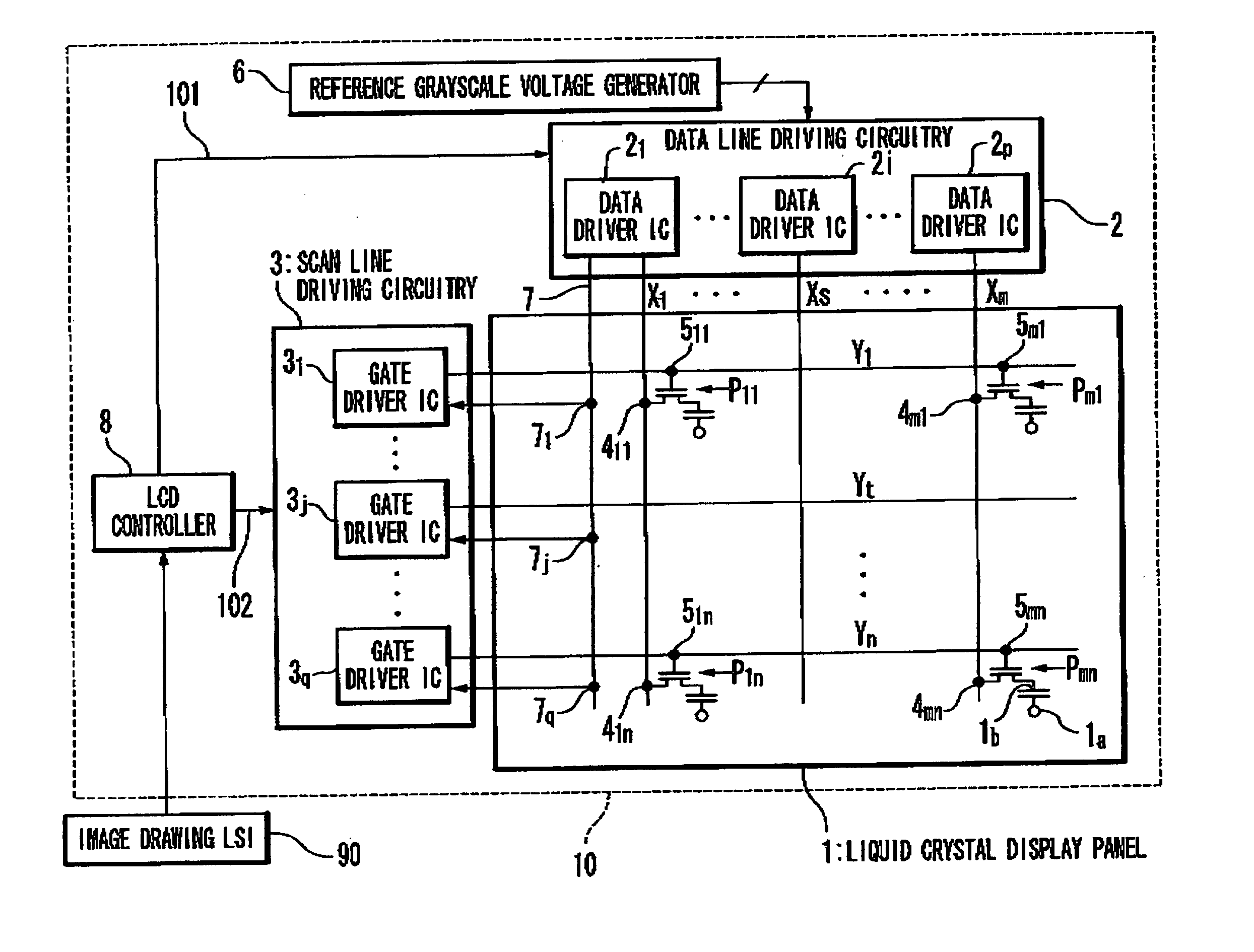
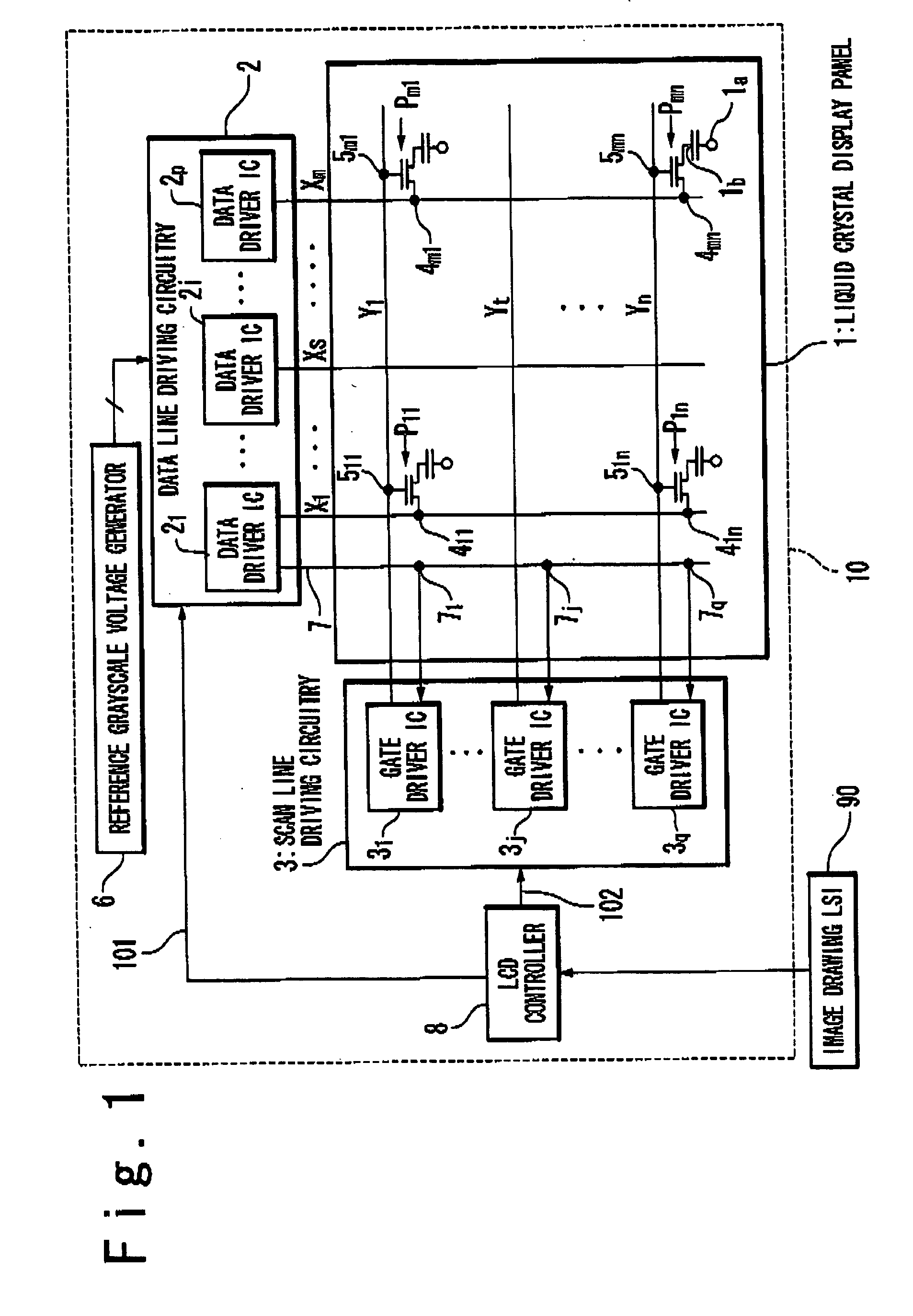
[0030]FIG. 1 is a block diagram showing the configuration of a liquid crystal display device 10 in one embodiment of the present invention. The liquid crystal display device 10 is provided with a liquid crystal display panel 1, a data line driving circuitry 2, a scan line driving circuitry 3, a reference grayscale voltage generator 6, an LCD (liquid crystal display) controller 8 and a power source circuit (not shown). On the liquid crystal display panel 1 provided are a set of data lines X1 to Xm extending in the column direction (m is a natural number of 2 or more), and a set of scan lines Y1 to Yn extending in the row direction (n...


PUM


Abstract

A display device is provided with a display panel, a data line driving circuitry, and a scan line driving circuitry. The display panel includes: a plurality of data lines extending in a column direction; a plurality of scan lines extending in a row direction; a plurality of pixels disposed at respective intersections of the plurality of data lines and the plurality of scan lines, and a dummy data line arranged in parallel to the plurality of data lines. The data line driving circuitry drives the plurality of data lines and the dummy data line. The scan line driving circuitry drives the plurality of scan lines. The data line driving circuitry feeds a dummy signal to the scan line driving circuitry through the dummy data line. The scan line driving circuitry drives the scan lines in response to the dummy signal.

Description

BACKGROUND OF THE INVENTION [0001] 1. Field of the Invention [0002] The present invention relates to a display device, a data driver IC, a gate driver IC and a scan line driving circuitry, in particular, a method of driving a large-size and high-resolution display panel. [0003] 2. Description of the Related Art [0004] In recent years, display panel devices have become widely used in various electronic devices that require lower operating voltage, lower power consumption, and reduced size and weight. In particular, liquid crystal display devices, which are advantageous in terms of reduced power consumption, weight and size, compared to other display devices, have been adopted as display devices in various electronic appliances, such as televisions and personal computer monitors. [0005] One typical liquid-crystal display device is the active matrix liquid crystal display device (AMLCD), which incorporates active elements such as TFT (Thin Film Transistor) in pixels. An active matrix l...

Claims


Application Information

Patent Timeline
IPC IPC(8): G09G3/36
CPCG09G3/3648G09G3/3677G09G3/3688G09G2320/0204
Inventor HASHIMOTO, YOSHIHARUHAYAMA, HIROSHIKUME, TORU
Owner RENESAS ELECTRONICS CORP
Why Eureka
Try Eureka