Exposure apparatus and exposure method, maintenance method, and device manufacturing method

a technology of exposure apparatus and manufacturing method, which is applied in the direction of photomechanical treatment, printing, instruments, etc., can solve the problems of malfunction of manufactured devices around substrates, and poor performance of exposure apparatus, so as to suppress the deterioration of the characteristics of exposure apparatus and favorable exposure of substrates

Inactive Publication Date: 2007-04-19
NIKON CORP
View PDF32 Cites 72 Cited by
  • Summary
  • Abstract
  • Description
  • Claims
  • Application Information

AI Technical Summary

Benefits of technology

[0008] An object of the present invention is to provide art exposure apparatus and an exposure method which can favorably expose a substrate. Furthermore, it is an object to provide a maintenance method which can suppress deterioration of the characteristics of the exposure apparatus. Moreover, it is an object to provide a device manufacturing method which can manufacture a device having a desired performance.

Problems solved by technology

If the liquid filling the optical path space of the exposure light is charged, there is a possibility that a disadvantage may arise where the performance of the exposure apparatus is worsened, or the performance of the manufactured device is worsened.
For example, if the liquid is charged, there is a possibility of a malfunction of electrical equipment provided around the substrate, or a deterioration of the pattern formed on the substrate.
Furthermore, when the substrate is exposed via the liquid in order to form the pattern on the substrate, if bubbles are present in the liquid filling the optical path of the exposure light, there is the possibility of exposure defects such as the occurrence of faults in the pattern formed on the substrate, thus inviting a deterioration of the performance of the manufactured device.

Method used


Image

  • Exposure apparatus and exposure method, maintenance method, and device manufacturing method
  • Exposure apparatus and exposure method, maintenance method, and device manufacturing method
  • Exposure apparatus and exposure method, maintenance method, and device manufacturing method

Examples


first embodiment

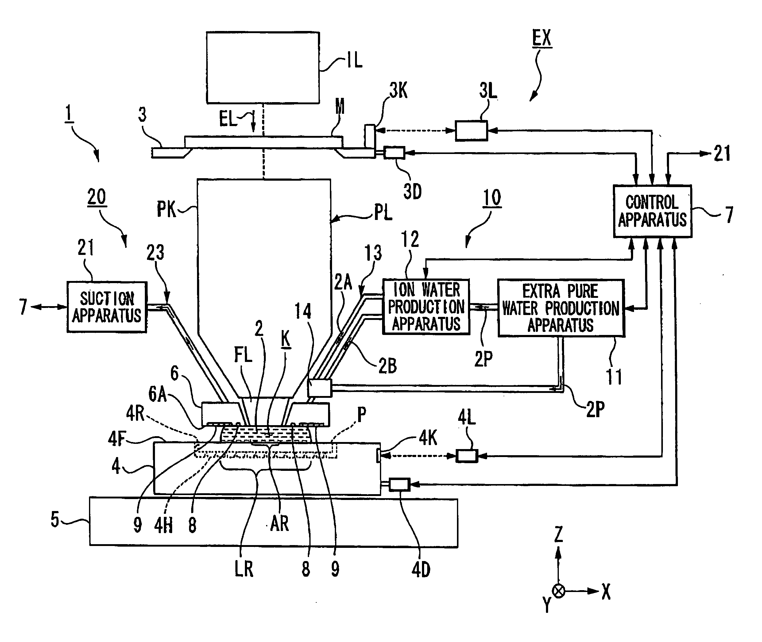
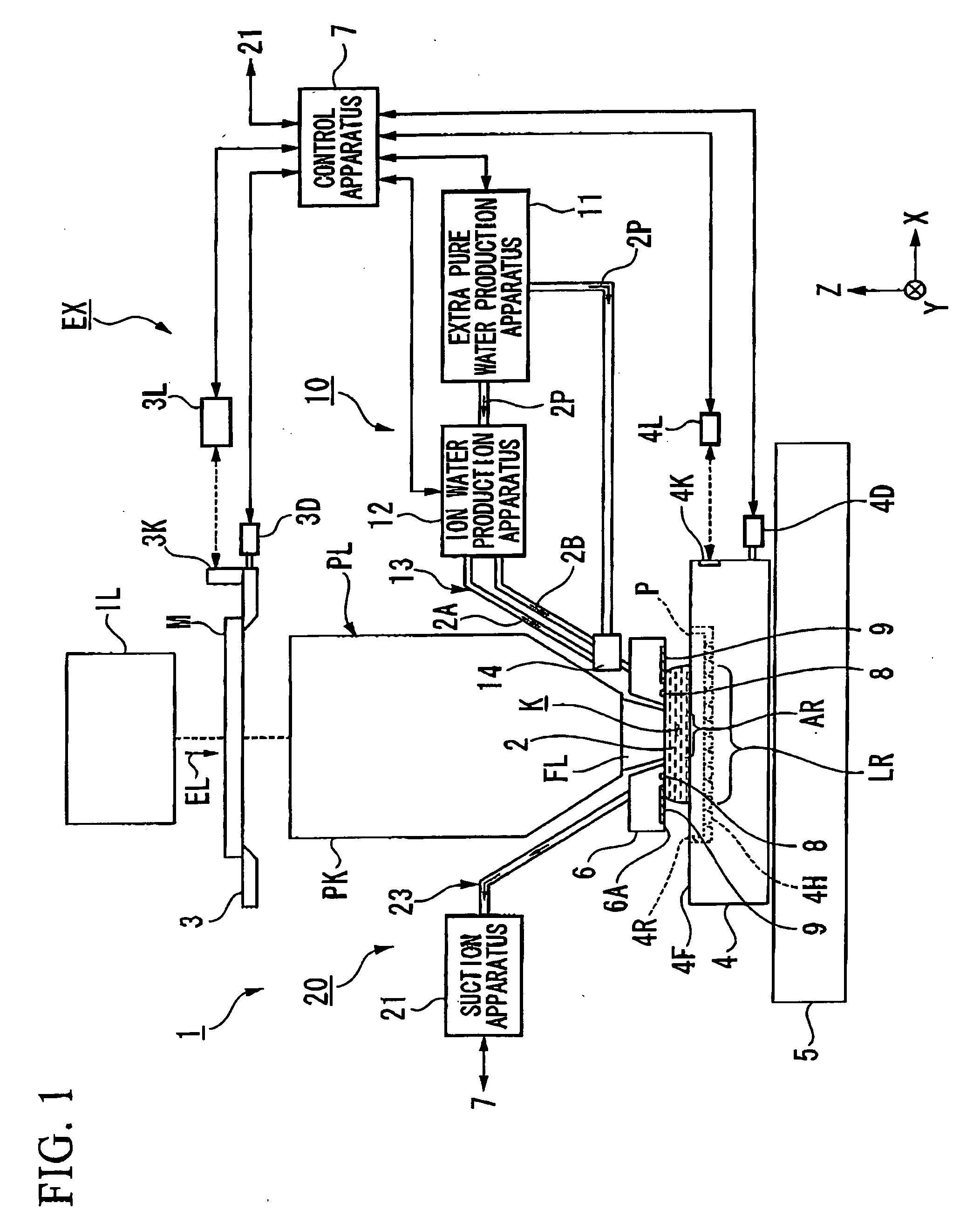
[0064] A first embodiment will be explained. FIG. 1 is a schematic block diagram showing an exposure apparatus EX according to a first embodiment. In FIG. 1, the exposure apparatus EX includes; a mask stage 3 capable of holding and moving a mask M, a substrate stage 4 capable of holding and moving a substrate P, an illumination optical system IL for illuminating a mask M held on the mask stage 3 with exposure light EL, a projection optical system PL for projecting a pattern of the mask M illuminated by the exposure light EL onto the substrate P, and a control apparatus 7 for controlling operation of the whole exposure apparatus EX. The substrate here includes one a sensitive material (photoresist) is spread on a substrate of a semiconductor wafer or the like, and includes a reticule formed with a device pattern which is reduction size projected onto the substrate. In the present embodiment, a transmission mask is used as the mask, however a reflecting mask may be used.

[0065] The ex...

second embodiment

[0117] Next is a description of a second embodiment. Components the same as or similar to those of the abovementioned embodiment are denoted by the same reference symbols, and description thereof is simplified or omitted.

[0118]FIG. 7 shows a liquid supply system 10 according to the second embodiment. In FIG. 7, the liquid supply system 10 includes; a first supply pipe 13A which flows either one of anode water 2A and cathode water 2B produced by an ion water production apparatus 12, and a fourth supply pipe 13D which flows extra pure water 2P which has not been ionized. Furthermore, a mixing apparatus 14 is provided in the vicinity of a nozzle member 6 (supply ports 8) for mixing the anode water 2A or the cathode water 21B which flows in the first supply pipe 13A, with the extra pure water 2P which is flowed in the fourth supply pipe 13D. The liquid 2 produced by the mixing apparatus 14 is supplied to the supply ports 8 via a third supply pipe 13C and a supply passage 8L.

[0119] In ...

third embodiment

[0123] Next is a description of a third embodiment. In the following description, components the same as or similar to those of the abovementioned embodiments are denoted by the same reference symbols, and description thereof is simplified or omitted. FIG. 8 shows a liquid supply system 10 according to the third embodiment. In FIG. 7, in a fourth supply pipe 13D through which the extra pure water 2P being the non ion water flows, a measuring device 18 is provided which can measure the charge state of the extra pure water 2P which flows in the fourth supply pipe 13D. The measuring device 18 can measure the charge amount of the extra pure water 2P which flows in the fourth supply pipe 13D. Furthermore, the measuring device 18 can measure if the extra pure water 2P which flows in the fourth supply pipe 13D is charged with a positive or a negative charge.

[0124] The control apparatus 7 controls the mixing operation in the mixing apparatus 14 based on the measurement results of the measu...


PUM


Abstract

An exposure apparatus includes; a supply outlet that supplies a liquid to an optical path space of exposure light, and a liquid supply system that supplies an ionized ionic liquid to the supply outlet.

Description

CROSS-REFERENCE TO RELATED APPLICATION [0001] This application is a non-provisional application claiming benefit of provisional application No. 60 / 751,306, filed Dec. 19, 2005, and claims priority to Japanese Patent Application Nos. 2005-180443, filed Jun. 21, 2005, and 2005-214317, filed Jul. 25, 2005, the contents of which are incorporated herein by reference.BACKGROUND OF THE INVENTION [0002] 1. Field of the Invention [0003] The present invention relates to an exposure apparatus and exposure method, a maintenance method for the exposure apparatus, and a device manufacturing method. [0004] 2. Description of Related Art [0005] In the photolithography process which is one manufacturing process for micro devices (electronic devices etc.) such as semiconductor devices and the like, an exposure apparatus is used which exposes a pattern image of a mask onto a photosensitive substrate. In the manufacture of a micro device, in order to increase the density of the device, it is necessary t...

Claims


Application Information

Patent Timeline
Patent Type & Authority Applications(United States)
IPC IPC(8): G03B27/42
CPCG03B27/42G03F7/70341
Inventor NAGAHASHI, YOSHITOMONAKANO, KATSUSHI
Owner NIKON CORP
Why Eureka
Try Eureka