
Power supply apparatus and power line communication apparatus

Inactive Publication Date: 2007-04-19
PANASONIC CORP
View PDF15 Cites 26 Cited by
  • Summary
  • Abstract
  • Description
  • Claims
  • Application Information

AI Technical Summary

Benefits of technology

[0018] The embodiment examples have taken the above-described problems, and aims to provide a power source apparatus and a power line communication apparatus capable of eliminating or simplifying a signal reduction circuit and of supplying power without attenuating a transmission signal.
[0020] The configuration above allows power supply to a power load and enables input and output of the communication signal via the transformer. The communication signal is prevented from flowing to a side of the power load. Thereby, power can be supplied to the power load without attenuating the communication signal, and the signal reduction circuit can be eliminated or simplified.
[0022] The configuration above allows power supply to the modem or to an external device with no attenuation of the communication signal, and thereby achieves the power line communication apparatus that requires no or a simplified signal reduction circuit.

Problems solved by technology

In power line communication that uses the power lines as the transmission lines, however, noise reduction circuit 940 reduces the impedance between the power lines and thus increases signal loss.
Further, capacitor C4 or switching regulator 930 is taken as a load for the transmission signal, thus leading to attenuation of the transmission signal.
However, it is difficult to make an inductor that constantly has high impedance in a wide signal range.
In addition, the stray capacitance, including the parallel capacitance component of the inductor between the transmission lines, hampers wideband use.
Particularly, a high-power-consumption device, such as the power source unit and the connected peripheral device, has a large inductor, thus causing large stray capacitance and significantly hampering wideband use.
Further, in a case when installed in the high-power-consumption device and in other cases, setting a large value so as to obtain high impedance causes magnetic saturation of a core and the like, and thus it is difficult to-obtain the high impedance.
It is difficult, however, to achieve such signal reduction circuit, particularly when the high-power-consumption device is connected.

Method used


Image

  • Power supply apparatus and power line communication apparatus
  • Power supply apparatus and power line communication apparatus
  • Power supply apparatus and power line communication apparatus

Examples


first embodiment

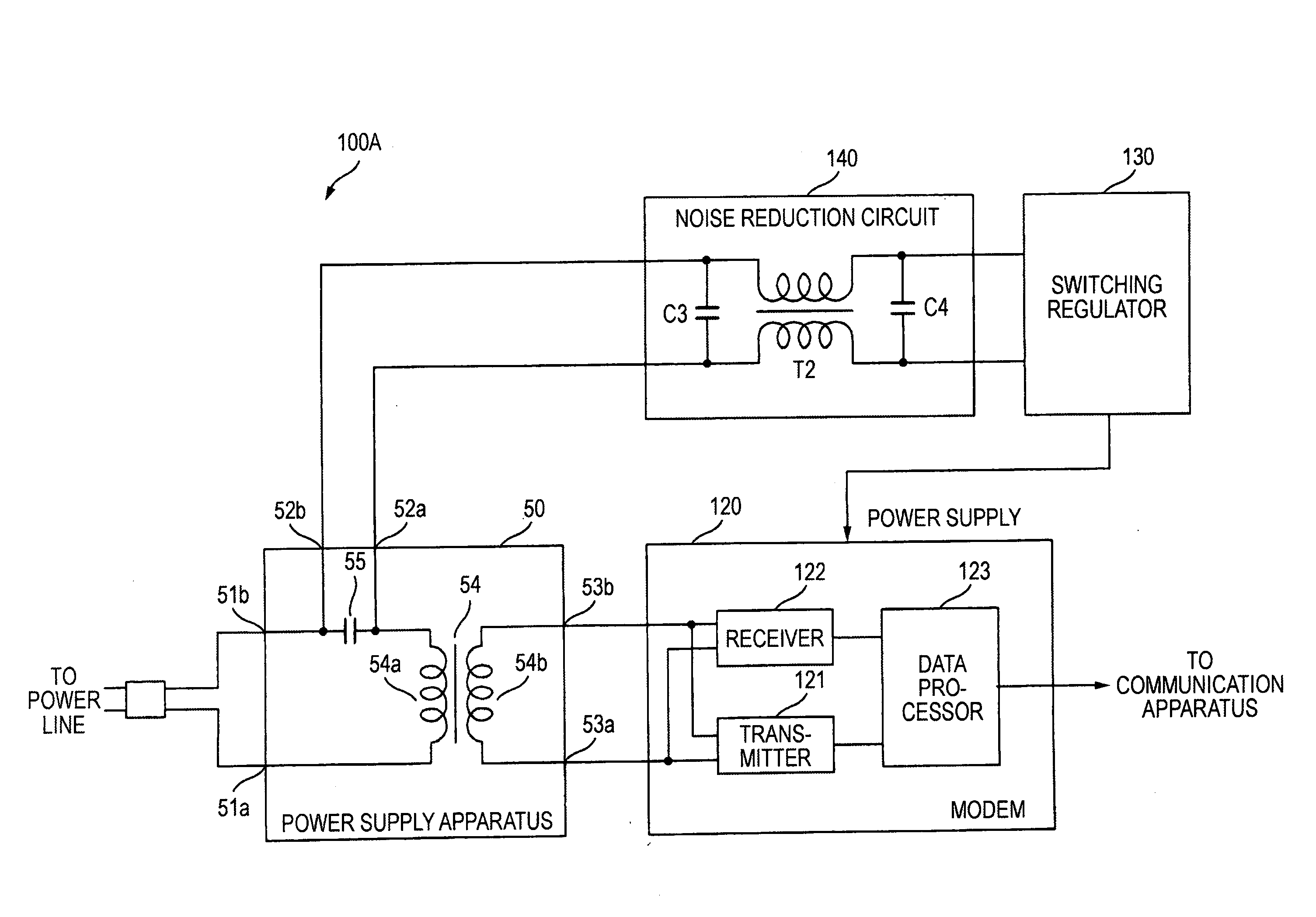
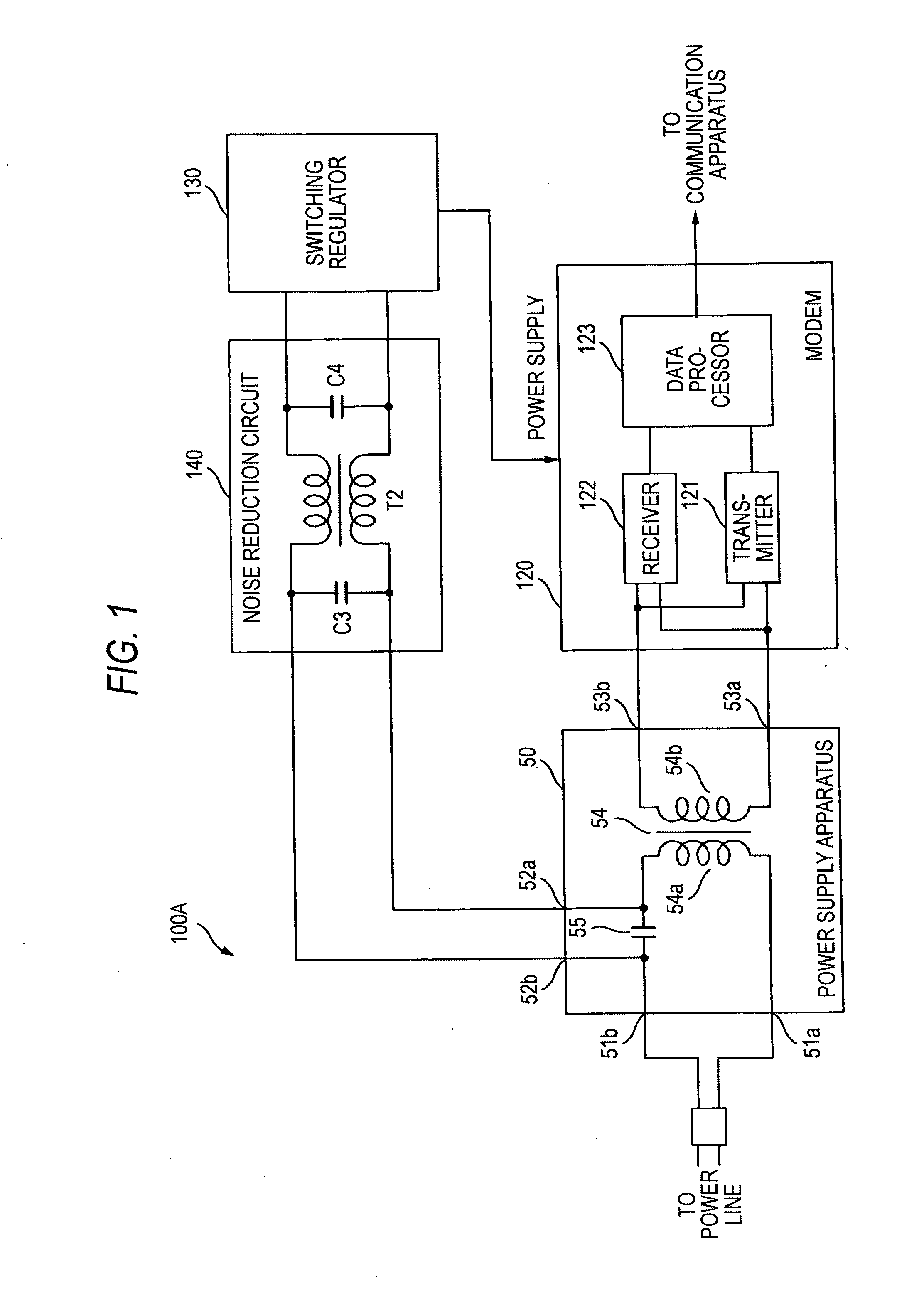
[0044]FIG. 1 illustrates a configuration of a power line communication apparatus provided with a power supply apparatus according to a first embodiment. Power line communication apparatus 100A includes power supply apparatus 50, modem 120, switching regulator 130, and noise reduction circuit 140. Switching regulator 130 is an example of regulator that generates direct voltage based on the predermined voltage such as 120 VAC.

[0045] Power supply apparatus 50 is connected to a power line via a commercial power outlet and the like. Power supply apparatus 50 supplies power to switching regulator 130 and transmits to modem 120 a communication signal of power line communication over the power line. Modem 120 is connected to an communication apparatus, such as a personal computer (PC), a video device, and an audio device. Switching regulator 130 generates a direct voltage of a predetermined value and supplies power to modem 120, an external peripheral device, and the like.

[0046] Power sup...

second embodiment

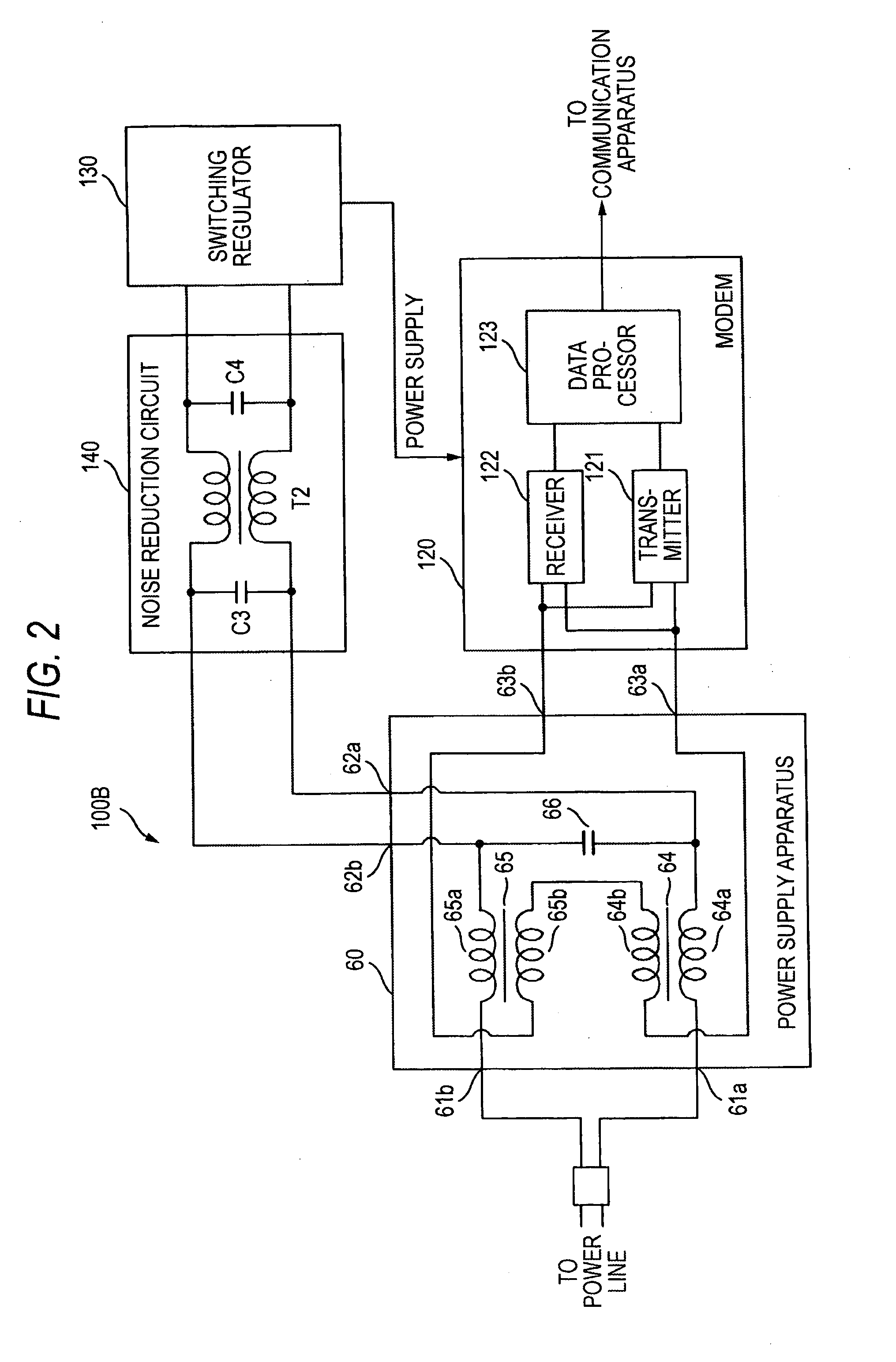
[0053]FIG. 2 illustrates a configuration of a power line communication apparatus provided with a power supply apparatus according to a second embodiment. Described in the second embodiment is another configuration example of the power supply apparatus. Power line communication apparatus 100B includes power supply apparatus 60, modem 120, switching regulator 130, and noise reduction circuit 140.

[0054] Power supply apparatus 60 of the second embodiment includes a pair of power reception terminals 61a and 61b, which correspond to a power receiver; a pair of power supply terminals 62a and 62b, which correspond to a power supplier; a pair of signal input / output terminals 63a and 63b, which correspond to a signal input / output unit; first coupled transformer 64 and second couple transformer 65 that input and output a communication signal; and capacitor 66 that has high impedance to a commercial power supply frequency and low impedance to a communication signal frequency. Primary winding 6...

third embodiment

[0060]FIG. 3 illustrates a configuration of a power line communication apparatus provided with a power supply apparatus according to a third embodiment. Described in the third embodiment is another configuration example of the power supply apparatus. Power line communication apparatus 100C includes power supply apparatus 70, modem 120, switching regulator 130, and noise reduction circuit 140.

[0061] Power supply apparatus 70 of the third embodiment includes a pair of power reception terminals 71a and 71b, which correspond to a power receiver; a pair of power supply terminals 72a and 72b, which correspond to a power supplier; a pair of signal input / output terminals 73a and 73b, which correspond to a signal input / output unit; coupled transformer 74 that inputs and outputs a communication signal, wherein a primary winding is divided into two; and capacitor 75 that has high impedance to a commercial power supply frequency and low impedance to a communication signal frequency. One power ...


PUM


Abstract

A power supply apparatus has a coupled transformer that inputs and outputs a communication signal and a capacitor that has high impedance to a commercial power supply frequency and low impedance to a communication signal frequency. The capacitor is connected between a primary winding of the coupled transformer and a power reception terminal. To both ends of the capacitor, a switching regulator is connected via a noise reduction circuit. To a secondary winding of the coupled transformer, a modem of a power line communication apparatus is connected. In the configuration, the coupled transformer and the switching regulator are thus connected in series.

Description

BACKGROUND [0001] 1. Field of the Invention [0002] An embodiment presented below relates to a power supply apparatus and a power line communication apparatus suitable as a power line communication apparatus that performs communication over a power line as a signal transmission line. [0003] 2. Description of Related Art [0004] To perform wired data communication at home, office, or factory using a terminal, such as a computer, for example, it is normally required to install wiring for cables and connectors used as transmission lines at required locations. A variety of installation works are thus required before starting operation of communication equipment. [0005] Meanwhile, a commercial power supply of, for example, 120 VAC (60 Hz) in the United States of America or 100 VAC (50 / 60 Hz) in Japan is mostly used at home, office, factory, and the like. Thus, power lines that supply the power are already installed across home, office, factory, and the like. Using the power lines for data ...

Claims


Application Information

Patent Timeline
IPC IPC(8): H04B1/16H02J3/02G05B11/01G08B23/00
CPCH04B3/54H04B3/56H04B2203/5454
Inventor ICHIHARA, FUMIO
Owner PANASONIC CORP
Learn More