Combustion engine including engine valve actuation system

a technology of combustion engine and valve actuator, which is applied in the direction of valve drive, non-mechanical valve, electrical control, etc., can solve the problems of undesirable emissions, exhaustion of undesirable emissions to the environment, and the need for an additional energy source for the supercharger

Inactive Publication Date: 2007-04-26
CATERPILLAR INC
View PDF99 Cites 8 Cited by
  • Summary
  • Abstract
  • Description
  • Claims
  • Application Information

AI Technical Summary

Problems solved by technology

While a turbocharger may utilize some energy from the engine exhaust, the series supercharger / turbocharger arrangement does not utilize energy from the turbocharger exhaust.
Furthermore, the supercharger requires an additional energy source.
The operation of an internal combustion engine, such as, for example, a diesel, gasoline, or natural gas engine, may cause the generation of undesirable emissions.
If no emission reduction measures are in place, these undesirable emissions will eventually be exhausted to the environment.
Unfortunately, the implementation of these emission reduction approaches typically results in a decrease in the overall efficiency of the engine.
However, a late intake Miller cycle may be undesirable under certain operating conditions.
For example, a diesel engine operating on a late intake Miller cycle may be difficult to start when the engine is cold.
This difficulty arises because diesel fuel combustion is achieved when an air and fuel mixture is pressurized to a certain level.
Thus, achieving combustion in a cold engine operating on a late intake Miller cycle may prove difficult.
Because the shape of the cam is fixed, this arrangement is inflexible and may not be changed during the operation of the engine.
In other words, a conventional cam driven valve actuation system may not be modified to account for different operating conditions of the engine.

Method used


Image

  • Combustion engine including engine valve actuation system
  • Combustion engine including engine valve actuation system
  • Combustion engine including engine valve actuation system

Examples


Embodiment Construction

[0039] Reference will now be made in detail to embodiments of the invention, examples of which are illustrated in the accompanying drawings. Wherever possible, the same reference numbers will be used throughout the drawings to refer to the same or like parts.

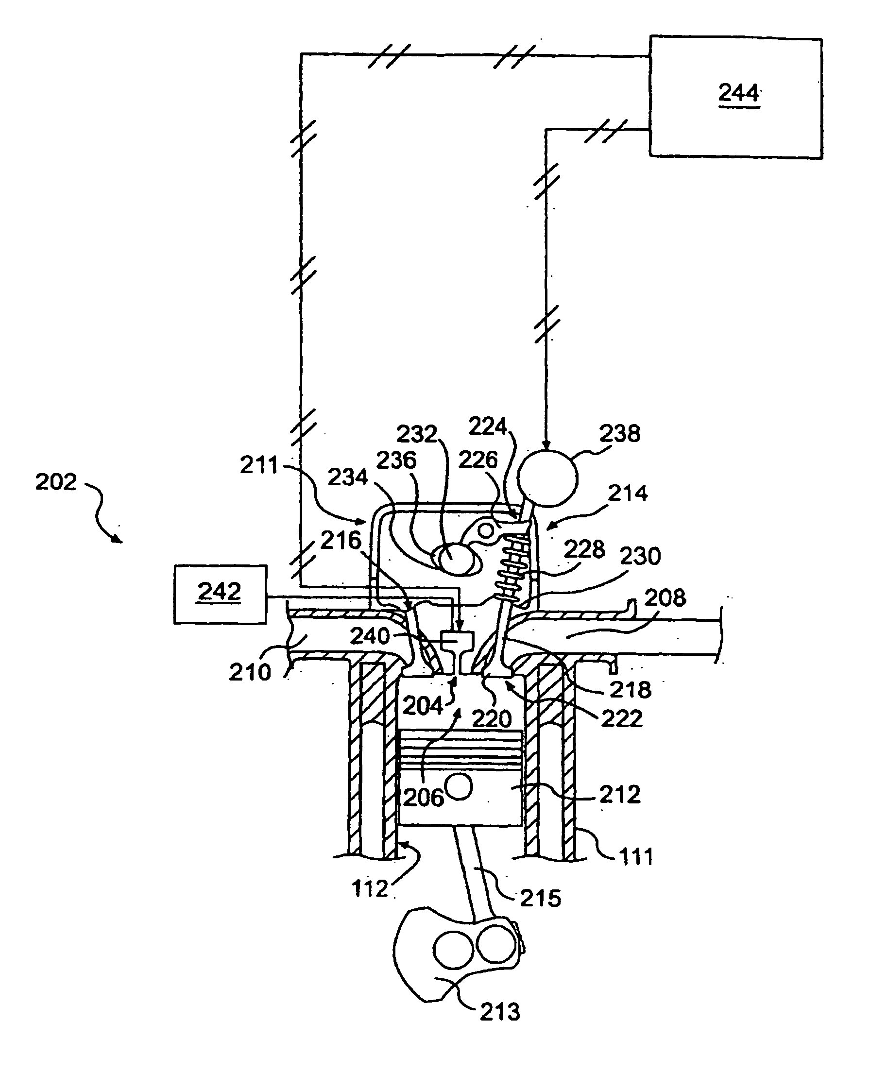
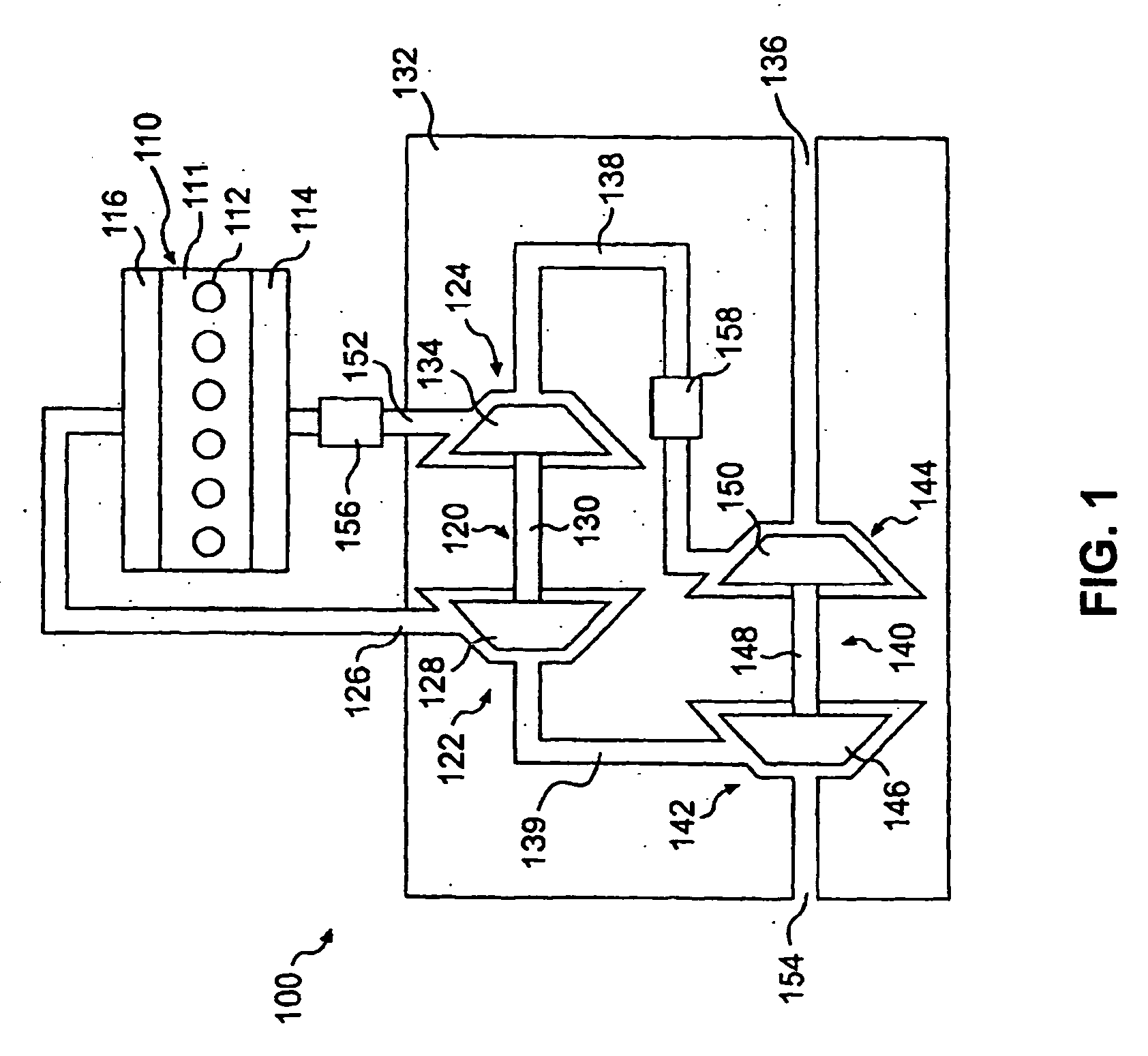
[0040] Referring to FIG. 1, an exemplary air supply system 244 for an internal combustion engine 110, for example, a four-stroke, diesel engine, is provided. The internal combustion engine 110 includes an engine block 111 defining a plurality of combustion cylinders 112, the number of which depends upon the particular application. For example, a 4-cylinder engine would include four combustion cylinders, a 6-cylinder engine would include six combustion cylinders, etc. In the exemplary embodiment of FIG. 1, six combustion cylinders 112 are shown. It should be appreciated that the engine 110 may be any other type of internal combustion engine, for example, a gasoline or natural gas engine.

[0041] The internal combustion engine 110...


PUM


Abstract

Engines and methods of controlling an engine may involve at least one fluid actuators associated with one or more engine intake and / or exhaust valves. Timing of valve closing / opening and use of an air supply system may enable engine operation according to a Miller cycle.

Description

RELATED APPLICATIONS [0001] This application is a continuation-in-part of U.S. patent application Ser. No. 10 / 933,300, filed Sep. 3, 2004, which is a continuation-in-part of U.S. patent application No. 10 / 733,570, filed Dec. 12, 2003, which is a continuation of U.S. patent application Ser. No. 10 / 143,908, filed May 14, 2002, now U.S. Pat. No. 6,688,280. This application is also a continuation-in-part of U.S. patent application Ser. No. 10 / 733,570, filed Dec. 12, 2003, which is a continuation of U.S. patent application Ser. No. 10 / 143,908, filed May 14, 2002. This application is also a continuation-in-part of a U.S. patent application Ser. No. 10 / 309,312, filed Dec. 4, 2002, which is a continuation-in-part of U.S. patent application Ser. No. 10 / 283,373, filed Oct. 30, 2002, which is a continuation-in-part of U.S. patent application Ser. No. 10 / 144,062, filed May 14, 2002. [0002] The entire disclosure of each of the U.S. patent applications mentioned in the preceding paragraph is inco...

Claims


Application Information

Patent Timeline
Patent Type & Authority Applications(United States)
IPC IPC(8): F02B33/44F02B29/04F02B47/08F02M25/07F02B3/00F02B75/02F01L1/34F02B37/013F02D13/02F02D41/00F02D41/40F02M57/02
CPCF01L1/08F01L9/02F01L9/04F01L2820/032F01L2820/033F01N3/035F01N3/106F02B29/04F02B29/0406F02B37/013F02B2275/14F02B2275/32F02D13/0226F02D13/0269F02D41/0002F02D41/0055F02D41/403F02D2041/001F02M25/0711F02M25/0718F02M25/0722F02M25/0724F02M25/0727F02M57/023Y02T10/123Y02T10/144Y02T10/142Y02T10/42F02B37/004F01N13/009F02M26/08F02M26/15F02M26/19F02M26/21F02M26/23F01L9/10F01L9/20Y02T10/12Y02T10/40
Inventor WEBER, JAMES R.LEMAN, SCOTT A.COLEMAN, GERALD N.DUFFY, KEVIN P.FLUGA, ERIC C.KILKENNY, JONATHAN P.CORNELL, SEAN O.
Owner CATERPILLAR INC
Why Eureka
Try Eureka