
Firearms projectile

a projectile and projectile technology, applied in the field of projectiles, can solve problems such as interface rupture, and achieve the effects of improving the performance of all small caliber weapons systems, reducing production costs, and reducing production costs

Active Publication Date: 2007-04-26
LIBERTY OPCO LLC
View PDF9 Cites 45 Cited by
  • Summary
  • Abstract
  • Description
  • Claims
  • Application Information

AI Technical Summary

Benefits of technology

[0010] Moreover, the projectile of the present invention eliminates the use of lead and the provision of an outer jacket. As such, specified portions of the exterior surface of the body of the projectile engage the rifling along an exterior surface area disposed and dimensioned to significantly reduce the area of contact of the projectile body with the rifling or interior surface of the barrel of the firearm. By reducing the contact area of the projectile, barrel friction is reduced thereby reducing heat buildup and improving barrel performance during sustained fire of the firearms. An additional benefit is the increase in barrel life and the reduction of fouling.
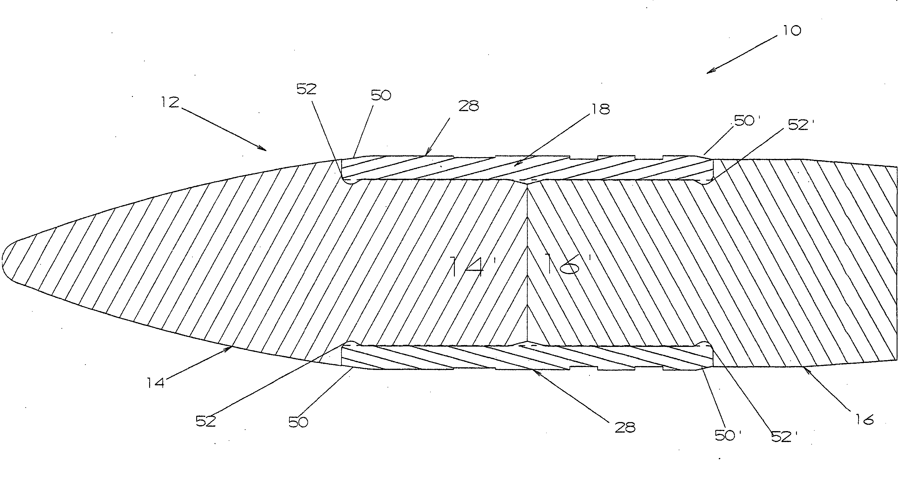
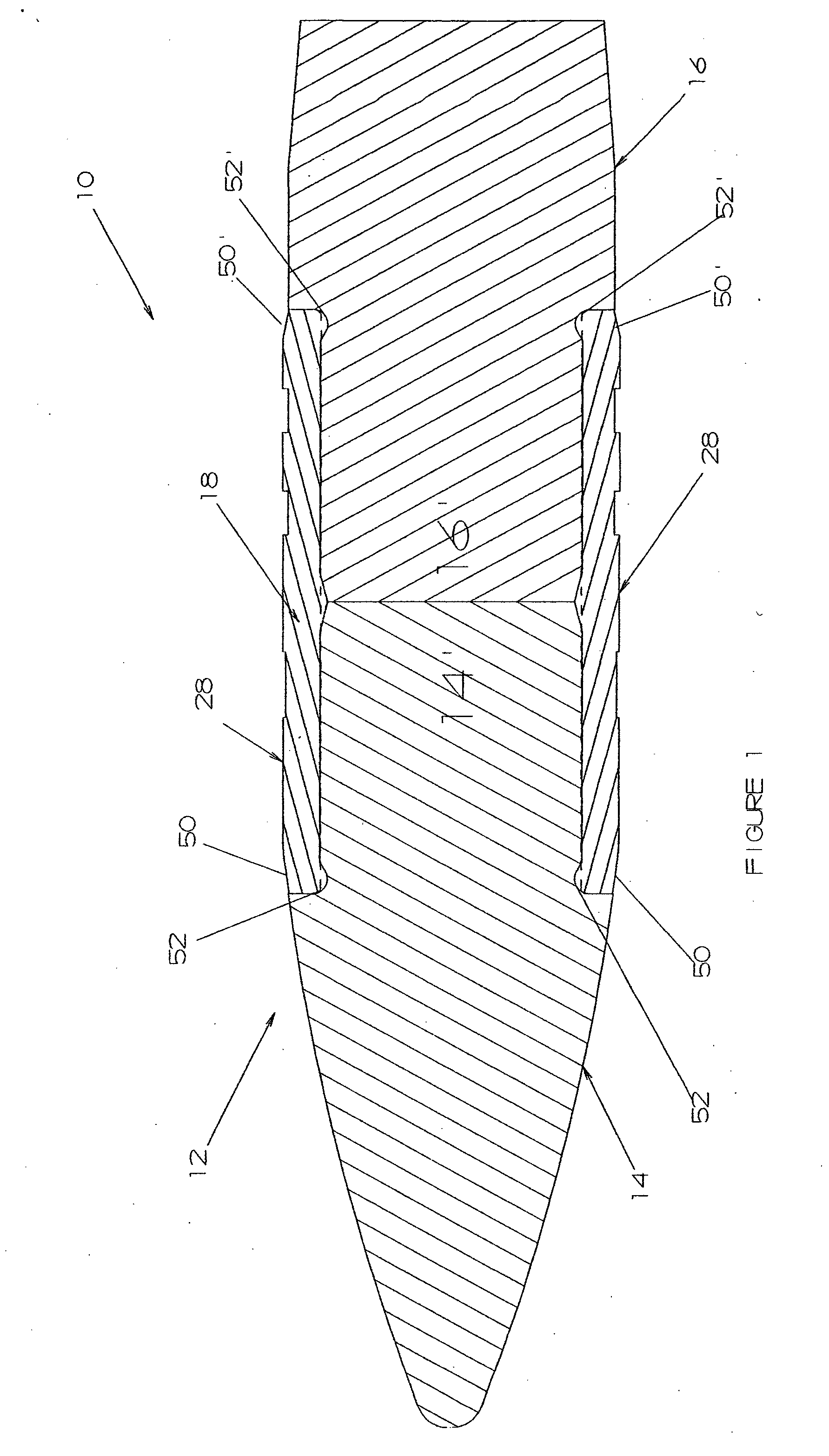
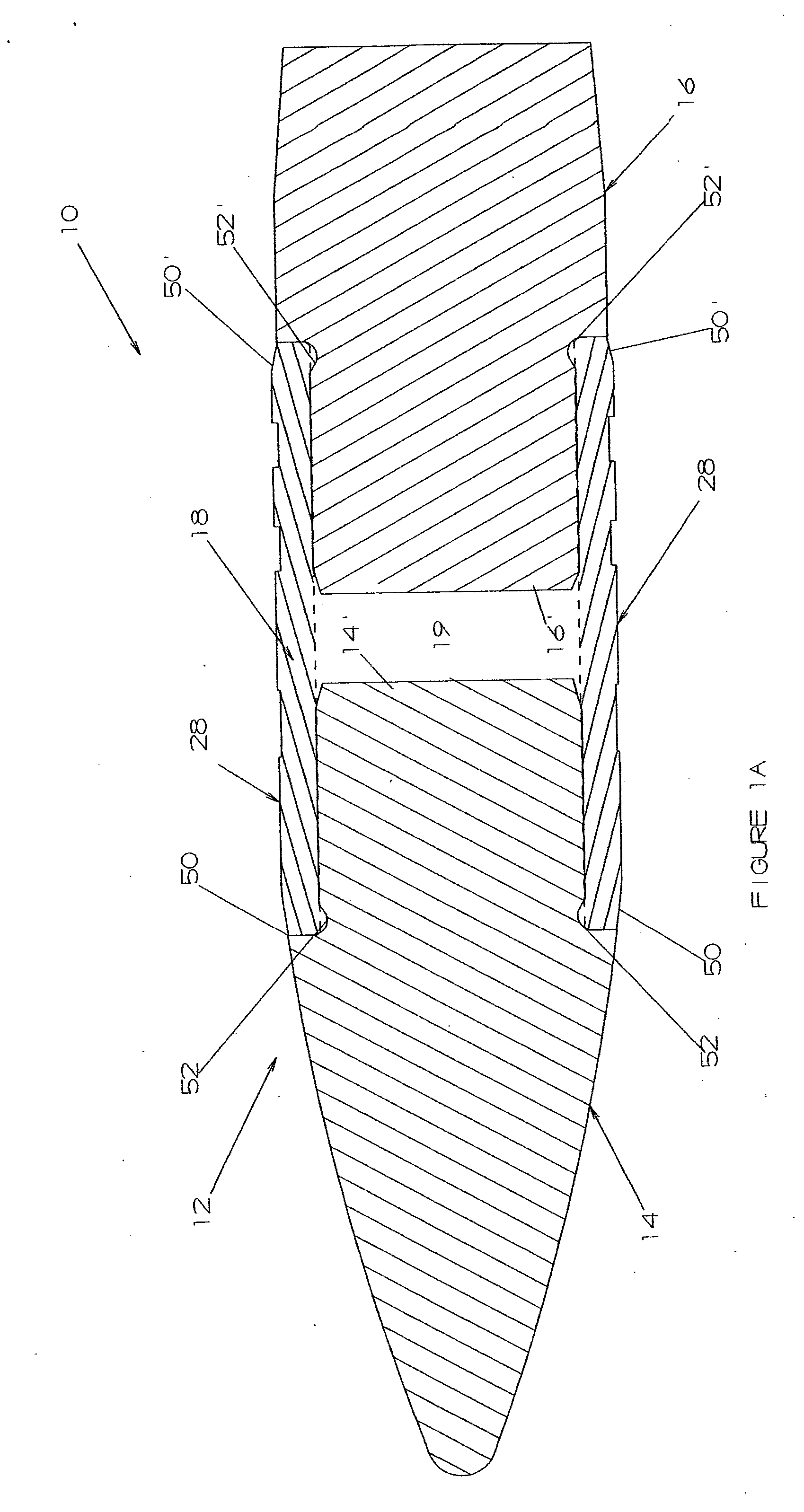
[0011] More specifically, the projectile of the present invention in one or more of the preferred embodiments to be described in greater detail hereinafter, comprises a body including a nose portion and a tail portion. In addition, the projectile body further includes an interface disposed intermediate opposite ends of the body and structured to interconnect the nose and tail portions in a manner which provides controlled fragmentation of the projectile body, especially when the projectile strikes a soft target. The disposition and structuring of the interface results in the positioning of an outer surface thereof so as to define the primary contact area between the body of the projectile and the rifling or interior surface of the barrel.
[0012] As set forth above, controlled fragmentation of the projectile, when striking at least a first predetermined target (soft material), is accomplished by the nose and tail portions of the projectile body being separable from one another. Such separation is facilitated by one or both of the nose and tail portions being removably attached or connected to the interface. Also, as will be explained in greater detail hereinafter, the interface is structured to rupture in certain instances such as, but not limited to, when the projectile strikes a predetermined target such as a human or animal target. More specifically, when the projectile body of the present invention penetrates a soft material target it begins to “tumble” typically resulting in the interface rupturing. As a result, the nose and tail portions separate from one another by means of the rupturing of the interface and / or the detachment of one or both of the nose and tail portions from the interface which may be facilitated by the rupturing of the interface.
[0014] The versatility of the manufacturing and performance characteristics of the projectile of the various embodiments of the present invention may also be attributed to the formation of the various nose and tail portions from high density metal matrix composites, metals or ceramics, wherein the interconnecting interface is preferably, but not necessarily, formed from a copper alloy. As a result, the projectile of the present invention may be produced on a mass scale using materials and manufacturing equipment currently available and known in the projectile production industry. Accordingly, production can occur in a relatively short period of time from initial startup and at a relatively modest expense, especially when compared to customized projectiles currently under investigation. Finally, the subject projectile can be produced in virtually all calibers from 0.17 through 50 BMG and can significantly improve the performance of all small caliber weapons systems with which it is used.

Problems solved by technology

More specifically, when the projectile body of the present invention penetrates a soft material target it begins to “tumble” typically resulting in the interface rupturing.

Method used


Image

  • Firearms projectile
  • Firearms projectile
  • Firearms projectile

Examples


Embodiment Construction

[0028] As shown in the accompanying Figures, the present invention is directed to a projectile generally indicated as 10 of the type structured to be fired from a firearm. More specifically, the projectile 10 includes a body, generally indicated as 12, which comprises a nose portion 14 and a tail portion 16 shown in detail in FIGS. 2, 3, 5, and 6 respectively. In addition, the projectile body 12 includes an interface 18, shown in detail in FIGS. 4 and 7, disposed intermediate the opposite ends of the projectile body 12 in interconnecting relation to the head portion 14 and the tail portion 16 as demonstrated in FIG. 1.

[0029] Structural features associated with one or more preferred embodiments of the projectile 10 include the nose and tail portions 14 and 16 respectively, formed of high density metal matrix composites, metals, alloys, or ceramics. More specifically, the nose and tail portions 14 and 16 can each be formed from a material which contains one or more of the following: ...


PUM


Abstract

A projectile structured to be discharged from a firearm comprising a body including a nose portion and a tail portion separable from one another when the projectile strikes a target. The body further includes an interface disposed intermediate opposite ends of the body of the projectile and structured to removably interconnect the nose and tail portions. Separation of the nose and tail portions such as when striking a soft tissue or like material target is caused by the tumbling of the projectile and the cooperative structuring of the interface to facilitate separation of the nose and tail portions. Further, the interface is disposed, dimensioned and structured to define the primary area of contact of the projectile body with the rifling or interior surface of the barrel of the firearm. At least one additional embodiment of the projectile comprises one of the nose or tail portions, preferably the tail portion structured to contain a supplemental payload which is carried to the target upon discharge of the firearm.

Description

BACKGROUND OF THE INVENTION [0001] 1. Field of the Invention [0002] This invention is directed to projectile structured to be discharged from a firearm and comprising separable nose and tail portions and an interconnecting interface. The interface is structured to facilitate concurrent, synchronization rotation of the nose portion, the interface and the tail portion as the projectile travels through the bore of the firearm and as it exits therefrom. The interface is dimensioned and disposed to define a reduced contact area of the projectile body with the rifling or interior surface of the barrel of the firearm. [0003] 2. Description of the Related Art [0004] The latter part of the twentieth century brought environmental concerns into the ammunition field. The resulting changes included the United States military reducing the use of copper jacketed lead projectiles in an effort to reduce lead contamination. In addition, Oak Ridge National Laboratory was given the task of finding a le...

Claims


Application Information

Patent Timeline
IPC IPC(8): F42B14/00
CPCF42B12/34
Inventor MARX, PJ
Owner LIBERTY OPCO LLC
Learn More