Forced-air-cooled engine equipped with cooling air guide cover

a technology of cooling air guide cover and engine, which is applied in the direction of machines/engines, combustion air/fuel air treatment, mechanical equipment, etc., can solve the problems of increasing the amount of heat generated, increasing the temperature of lube oil, and reducing the surface from which to release heat, so as to reduce assembly man-hour, increase durability, and facilitate assembly

Active Publication Date: 2007-04-26
MITSUBISHI HEAVY IND MEIKI ENGINES CO LTD
View PDF6 Cites 30 Cited by
  • Summary
  • Abstract
  • Description
  • Claims
  • Application Information

AI Technical Summary

Benefits of technology

[0022] The cooling air guide cover constructed as mentioned above can be easily assembled to the engine in a short time and contributes to largely reduce assembling man-hour. A forc...

Problems solved by technology

However, the cylinder air-guide cover and exhaust air guides cover only the cylinder and cylinder head and not cover the crankcase part to guide cooling air, and the crankcase part is cooled by natural cooling by the ambient air.
However, the amount of heat generated increase and the surface from which to release heat decreases as engines of this kind are small sized and high powered, so lube oil temperature tends to become higher.
Particularly, under high temperature environment, the temperature o...

Method used


Image

  • Forced-air-cooled engine equipped with cooling air guide cover
  • Forced-air-cooled engine equipped with cooling air guide cover
  • Forced-air-cooled engine equipped with cooling air guide cover

Examples


Embodiment Construction

[0032] A preferred embodiment of the present invention will now be detailed with reference to the accompanying drawings. It is intended, however, that unless particularly specified, dimensions, materials, relative positions and so forth of the constituent parts in the embodiments shall be interpreted as illustrative only not as limitative of the scope of the present invention.

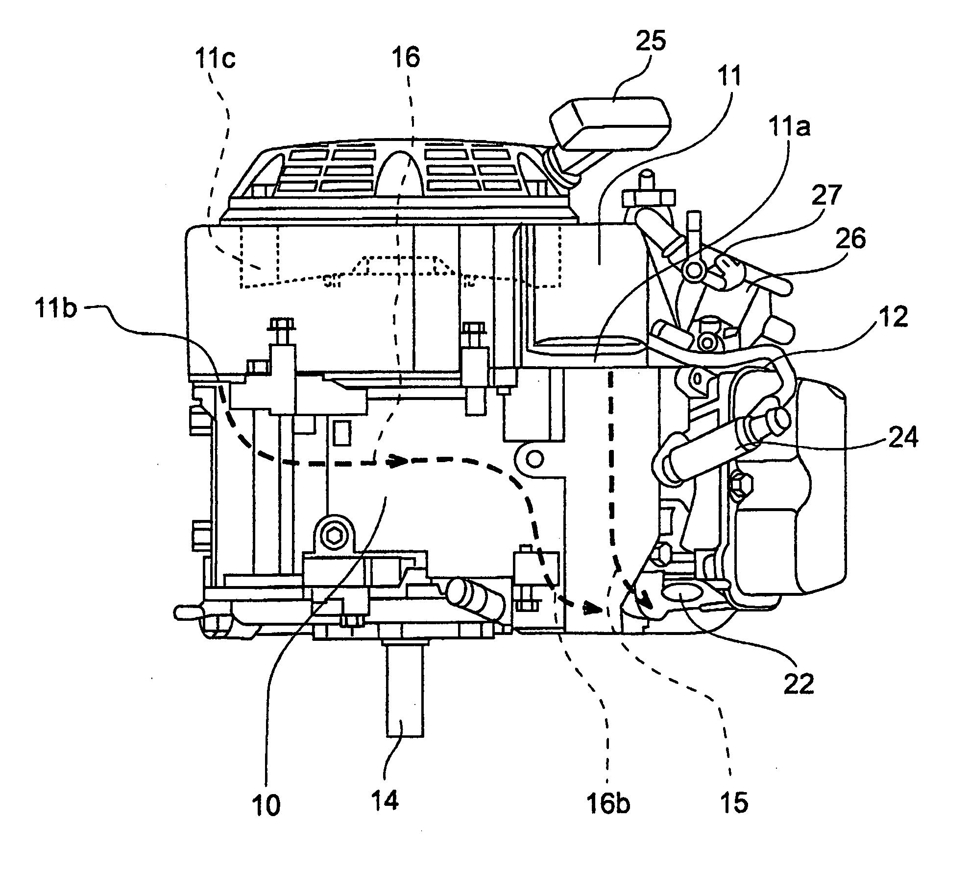
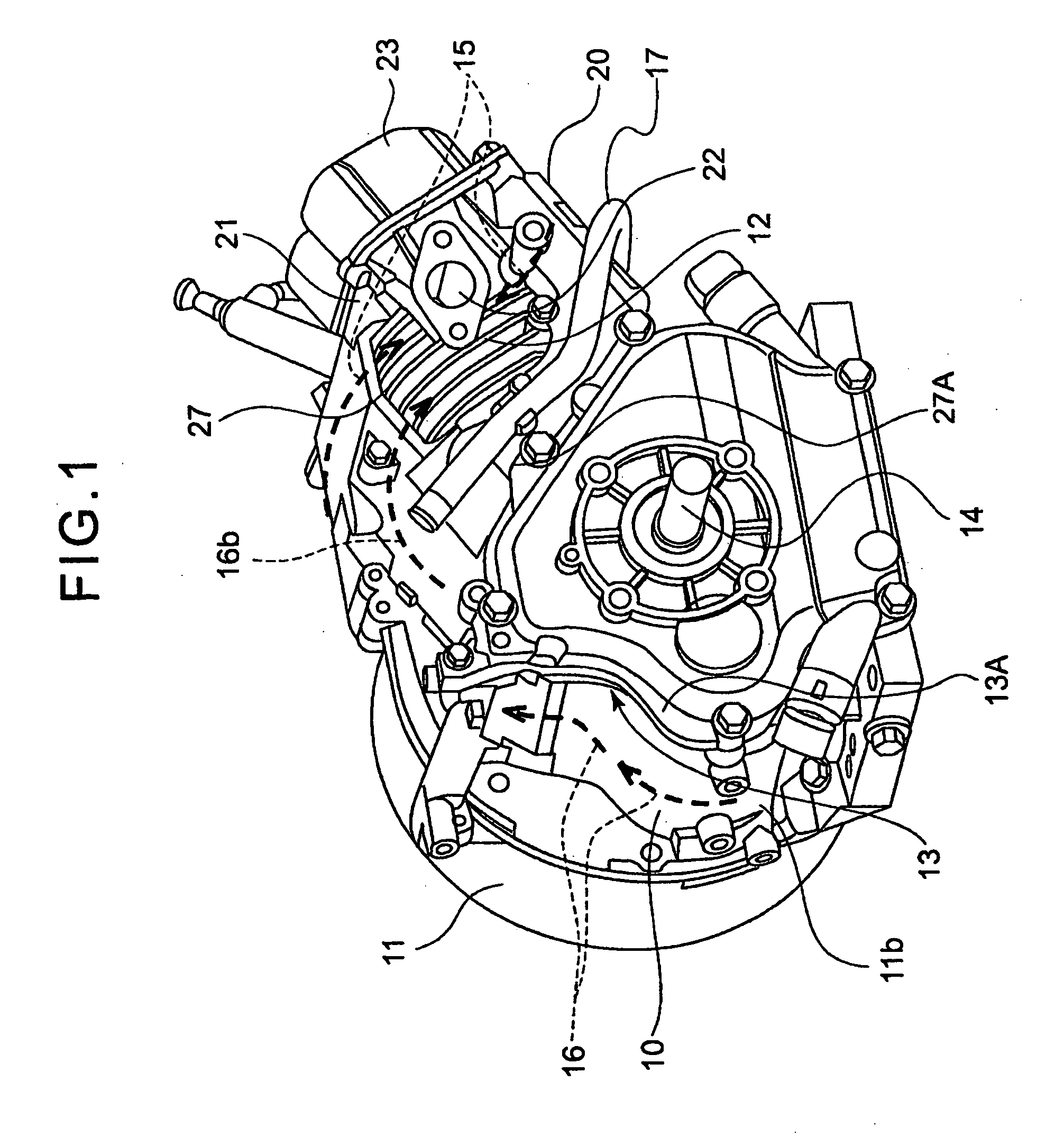
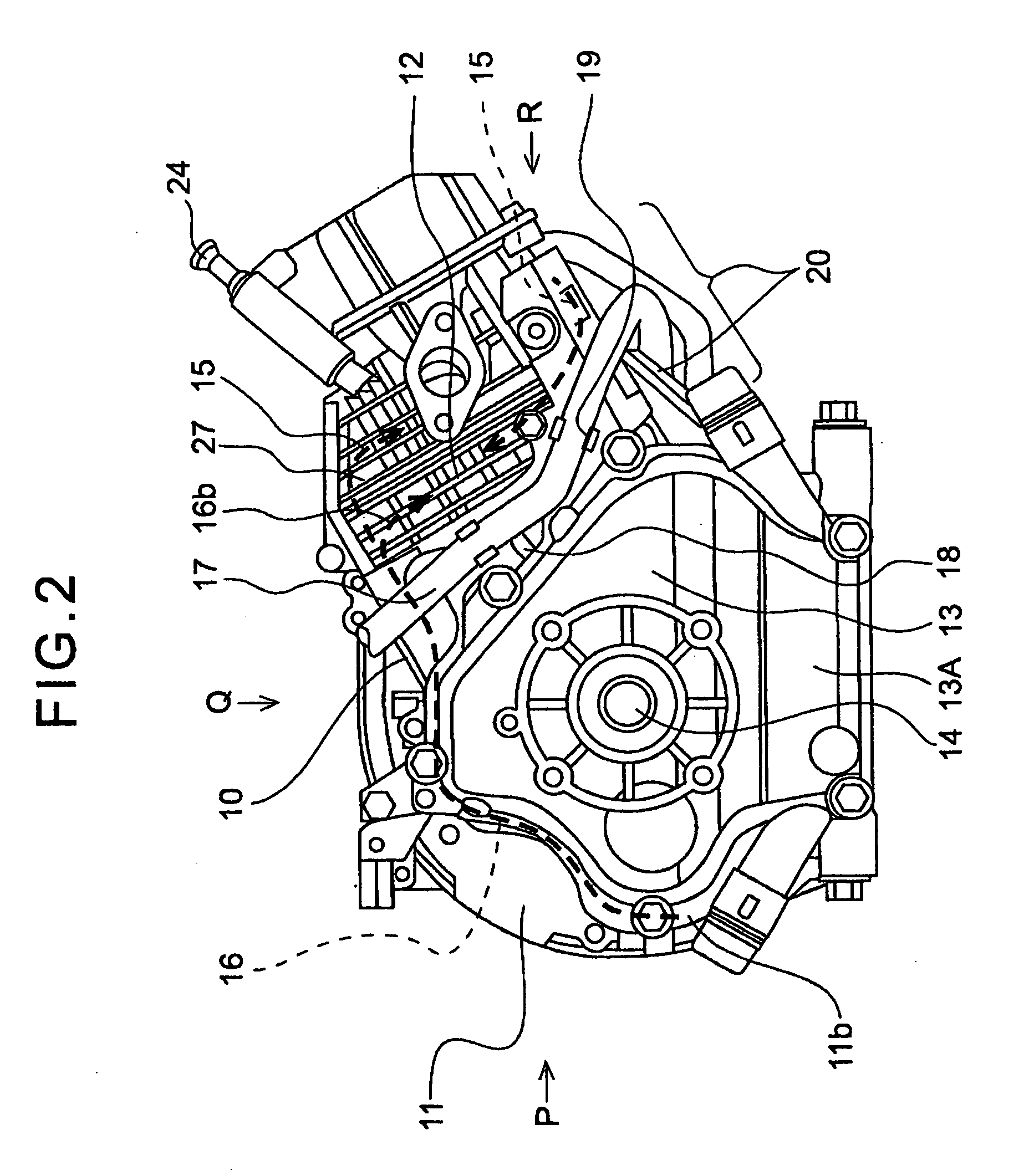
[0033]FIG. 1 is a perspective view of an engine to which the present invention applied with the fuel tank, air cleaner, muffler, controlling device, etc. omitted, and cooling air flow is shown.

[0034] In FIG. 1, reference numeral 13 is a crankcase-integrated cylinder block composed of a cylinder part 27 and a crankcase part 13A formed into one block. Reference numeral 21 is a cylinder head fixed on top of the cylinder part 27, 12 are cooling fins of the cylinder part including cooling fins of the cylinder head. Reference numeral 22 is an exhaust outlet of the cylinder head, 23 is a cylinder head cover, 24 is a...


PUM


Abstract

A forced-air-cooled engine having a main blow-out opening provided to a back plate of a cooling fan cover at a position facing a cylinder part for blowing out cooling air for cooling a cylinder part and a secondary blow-out opening provided to the back plate at a position opposite to the main blow-out opening in regard to the crankshaft center for cooling a part of a crankcase part, wherein a cooling air guide cover is equipped which is composed of a cylinder air-guide cover part which guides air blown out from the main blow-out opening to flow to cool the cylinder part and cylinder head, and a top cover part which guides air blown out from the secondary blow-out opening to flow along a side face of the crankcase part to cool there and then flow into midstream of the cooling air flow blown out from the main blow-out opening and cooling the cylinder part and cylinder head.

Description

BACKGROUND OF THE INVENTION [0001] 1. Field of the Invention [0002] The present invention relates to a forced-air-cooled engine composed of a cylinder block integrated with a crankcase, which is a single block integrating a crankcase part and a cylinder part that extend aslant from the crankcase part, particularly to a cooling air guide cover for distributing the cooling air effectively to improve cooling of the engine. [0003] 2. Description of the Related Art [0004] In a single cylinder, forced-air-cooled engine, air energized by the cooling fan attached to an end of the crankshaft blown out from the opening of the fan cover, the air is guided to the cylinder and cylinder head having a plurality of cooling fins around their outer surfaces to flow through the spaces between the fins to cool the cylinder and cylinder head. [0005] In Japanese Laid-Open Patent Application No. 2003-56408 is disclosed as such an engine an inclined cylinder type engine having a crankcase-integrated cylind...

Claims


Application Information

Patent Timeline
IPC IPC(8): F01P1/02F02M35/02
CPCF01P1/02F01P1/06F01P5/06F02B63/02Y02T10/166Y02T10/12
Inventor KOCHI, HIROYOSHISEKIMUKAI, MANABUMARUTA, YOSUKE
Owner MITSUBISHI HEAVY IND MEIKI ENGINES CO LTD
Why Eureka
Try Eureka