Heating resistance element, thermal head, printer, and method of manufacturing heating resistance element

a technology of heating resistors and heat radiation, which is applied in the direction of printing, etc., can solve the problems of heat radiation from the substrate not keeping up with heat transfer, heat transfer to the surface side of the heating resistor, and the whole thermal head is brought up to a considerable high temperature, so as to achieve stable quality, low manufacturing cost, and low power consumption

Inactive Publication Date: 2007-04-26
SEIKO INSTR INC
View PDF2 Cites 18 Cited by
  • Summary
  • Abstract
  • Description
  • Claims
  • Application Information

AI Technical Summary

Benefits of technology

[0017] The present invention is made in view of the above-mentioned circumstances. An object of the present invention is to provide a heating resistance element for improving the heating efficiency Of the heating resistors to reduce power consumption, improving the strength of a substrate under the heating resistors, and enabling simple manufacture at a low cost, a thermal head and a printer using the heating resistance element, and a method of manufacturing a heating resistance element.

Problems solved by technology

Further, when a thermal head continuously performs print output, since heat is continuously transferred to the substrate, heat radiation from the substrate cannot keep up with the heat transfer, and the whole thermal head is brought up to a considerably high temperature.
Because this temperature rise is a cause of deterioration of print quality, in order to materialize high quality continuous printing, it is necessary to increase the heating efficiency of the thermal head.
Accordingly, since the amount of heat transferred to a surface side of the heating resistors is small, the heating efficiency is low.
Second, dimensional precision of the resin material to be vaporized for forming the hollow portion is low, so a precisely shaped hollow portion cannot be formed.
Therefore, because the hollow portion is formed to be band-like across the plurality of heating resistors along the direction of arrangement of the plurality of heating resistors, the strength of the underglaze layer at the positions of the heating resistors is low, and thus, the hollow portion is liable to crush due to pressure applied to the heating resistors in printing.
In particular, because a drum, which sandwiches printing paper with the heating resistors, is disposed along the direction of arrangement of the heating resistors, there is a fear that the underglaze layer cracks along the direction of arrangement of the heating resistors.
Therefore, complicated processes are necessary for providing the hollow portion under the heating resistors, and requires much time in manufacture.

Method used


Image

  • Heating resistance element, thermal head, printer, and method of manufacturing heating resistance element
  • Heating resistance element, thermal head, printer, and method of manufacturing heating resistance element
  • Heating resistance element, thermal head, printer, and method of manufacturing heating resistance element

Examples


first embodiment

[First Embodiment]

[0101] This embodiment shows an example where the present invention is applied to a thermal printer.

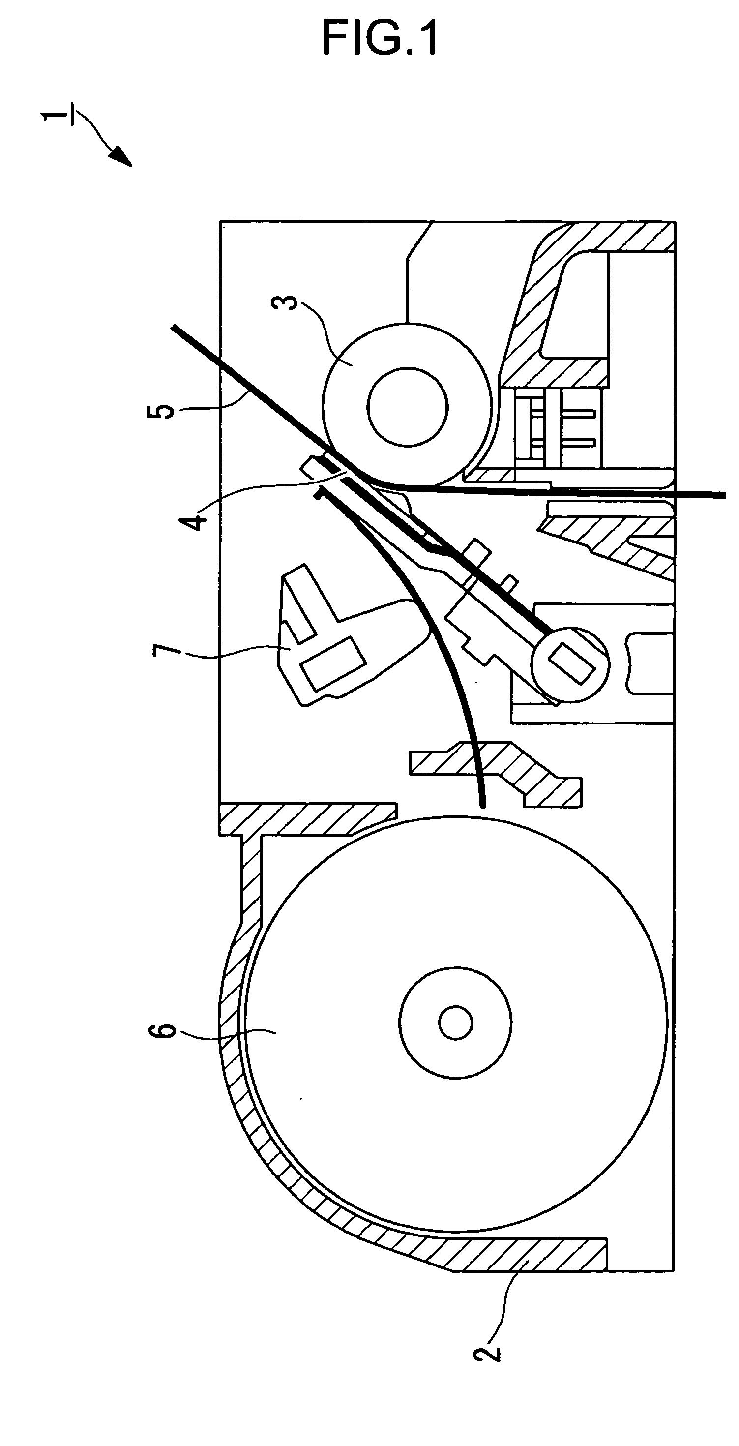
[0102] As illustrated in FIG. 1, a thermal printer 1 according to this embodiment is provided with a body frame 2, a platen roller 3 horizontally disposed, a thermal head 4 (heating resistance element) disposed so as to be opposed to an outer peripheral surface of the platen roller 3, a paper feed mechanism 6 for feeding a thermal paper 5 between the platen roller 3 and the thermal head 4, and a pressure mechanism 7 for pressing the thermal head 4 against the thermal paper 5 with predetermined pressing force.

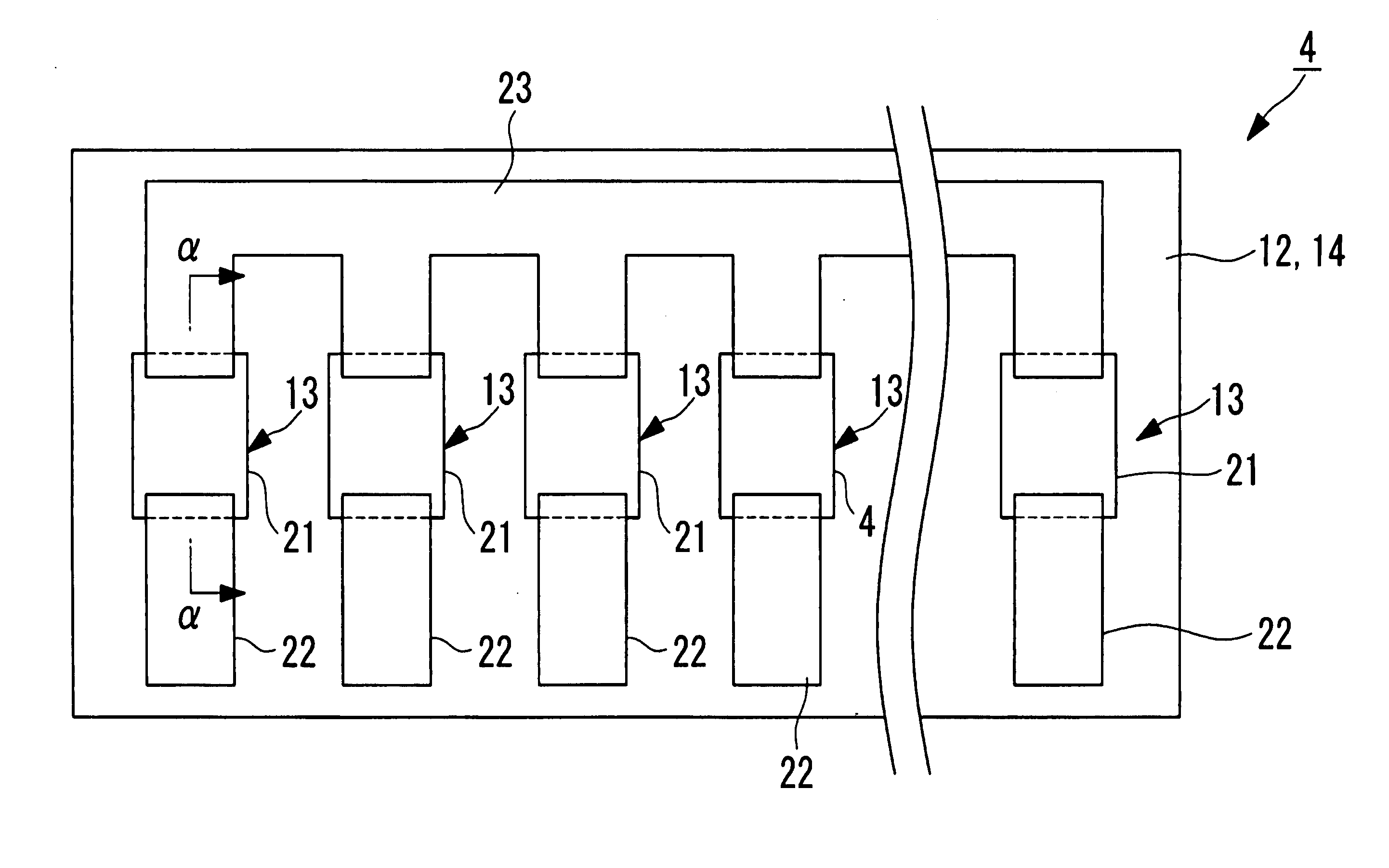
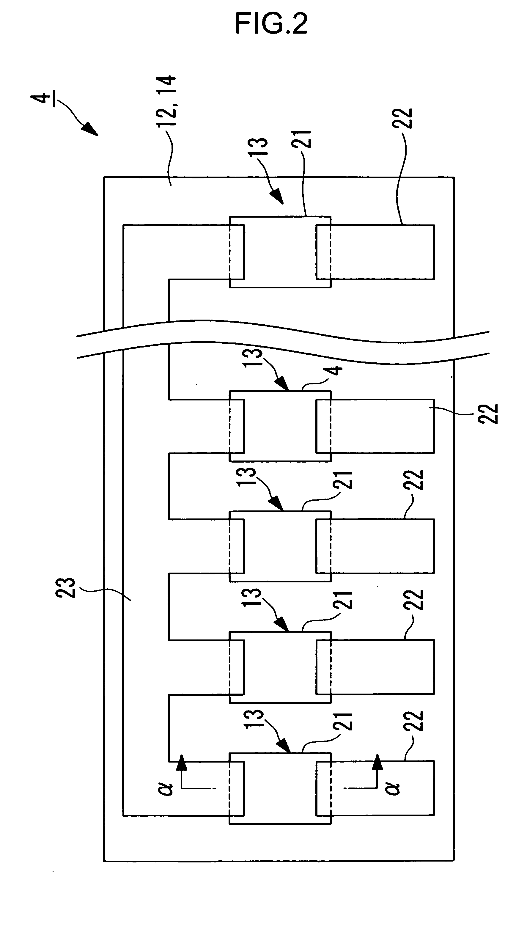
[0103] The thermal head 4 is plate-like as illustrated in a plan view of FIG. 2, and as illustrated in a sectional view of FIG. 3 (a sectional view taken along the line α-α of FIG. 2 and viewed in the direction of arrows α of FIG. 2), has a substrate 11, a thermal storage layer 12 formed on one surface side of the substrate and made of, for example, glass, a he...

second embodiment

[Second Embodiment]

[0148] A second embodiment of the present invention is described in the following with reference to FIG. 7.

[0149] A thermal printer illustrated in this embodiment uses a thermal head 31 instead of the thermal head 4 in the thermal printer 1 illustrated in the first embodiment.

[0150] In the following, as to the similar or identical members to the thermal head 4 illustrated in the first embodiment, the same symbols are used to designate the members and detailed description thereof is omitted.

[0151] The thermal head 31 is provided with a thermal storage layer 32 instead of the thermal storage layer 12 in the thermal head 4.

[0152] The thermal storage layer 32 is provided with a reflection layer 33 provided at a position spaced apart from the surface of the thermal storage layer 12 where the heating resistors 13 are formed along the surface.

[0153] Here, the reflection layer 33 may be formed by a metal layer, an organic layer, a colored glass layer, or the like.

[0...

third embodiment

[Third Embodiment]

[0161] A third embodiment of the present invention is described in the following with reference to FIG. 8.

[0162] A thermal printer illustrated in this embodiment uses a thermal head 51 instead of the thermal head 4 in the thermal printer 1 illustrated in the first embodiment.

[0163] In the following, as to the similar or identical members to the thermal head 4 illustrated in the first embodiment, the same numerals are used to designate the members and detailed description thereof is omitted.

[0164] The thermal head 51 is provided with a thermal storage layer 52 instead of the thermal storage layer 12 in the thermal head 4.

[0165] In the thermal storage layer 52, the hollow portions 26 are distributed also in a thickness direction of the thermal storage layer 12. More specifically, the density of the hollow portions 26 in the thermal storage layer 52 decreases as the hollow portions 26 approaches the surface where the heating resistors 13 are formed. In FIG. 8, an ...


PUM

PropertyMeasurementUnit
distanceaaaaaaaaaa
diameteraaaaaaaaaa
thicknessaaaaaaaaaa

Abstract

A thermal head is structured to have a substrate, a thermal storage layer formed on one surface of the substrate and made of glass, and heating resistors provided on the thermal storage layer. A plurality of hollow portions are formed at a position spaced apart from a surface where the heating resistors are formed by laser processing using a femtosecond laser, in an area of the thermal storage layer which is opposed to the heating resistors. In this way, to provide a heating resistance element for improving heating efficiency of heating resistors to reduce power consumption, improving strength of a substrate under the heating resistors, and for enabling simple manufacture at a low cost, a thermal head and a printer using the same, and a method of manufacturing a heating resistance element.

Description

BACKGROUND OF THE INVENTION [0001] 1. Field of the Invention [0002] The present invention relates to a heating resistance element, a thermal head and a printer using the same, and a method of manufacturing a heating resistance element. [0003] 2. Related Background Art [0004] A heating resistance element is used in, for example, a thermal head of a thermal printer. In a typical structure, a thermal storage layer made of glass or the like is provided on a substrate made of alumina ceramic or the like, and a plurality of heating resistors are provided on the thermal storage layer. [0005] Here, a thermal printer is a generic name for a thermal transfer printer for transferring ink heated and fused by a thermal head onto an object to be printed, a direct thermal printer for directly forming an image on thermal paper by a thermal head, and the like. [0006] In a thermal printer, by making heating resistors of a thermal head to selectively generate heat, and by applying heat to an object to...

Claims


Application Information

Patent Timeline
Patent Type & Authority Applications(United States)
IPC IPC(8): B41J2/335
CPCB41J2/33585
Inventor SHOJI, NORIYOSHISATO, YOSHINORIMOROOKA, TOSHIMITSU
Owner SEIKO INSTR INC
Why Eureka
Try Eureka