Total internal reflection micro lens array

a micro-lens array and internal reflection technology, applied in the field of optical devices, can solve the problems of limited angle of divergence of output beam, insufficient angle of divergence, and inability to gain angles

a micro-lens array and internal reflection technology, applied in the field of optical devices, can solve the problems of limited angle of divergence of output beam, insufficient angle of divergence, and inability to gain angles

US20070091444A1Inactive Publication Date: 2007-04-26SAMSUNG ELECTRONICS CO LTD

Image

  • Total internal reflection micro lens array
  • Total internal reflection micro lens array
  • Total internal reflection micro lens array

Examples


Embodiment Construction

[0025] The essence of the claimed invention is further explained on the basis of the following drawings.

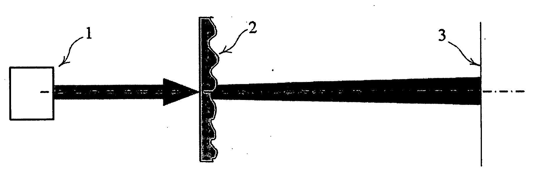
[0026]FIG. 1 shows the optical arrangement of the claimed device, where 1 is the light source, 2 is the micro lens array, and 3 is the plane of analysis.

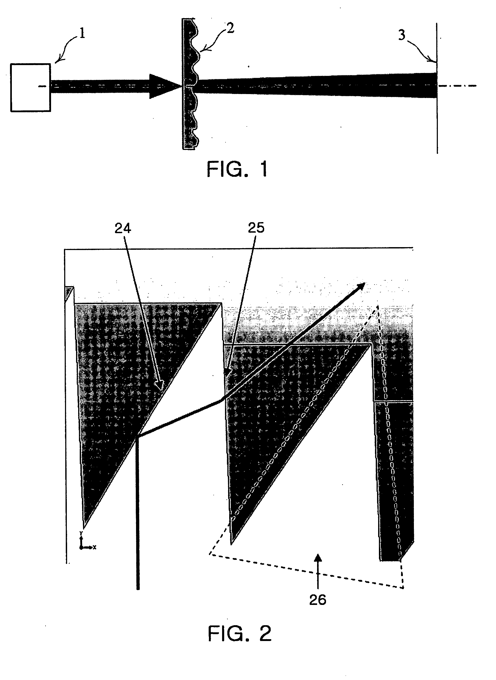
[0027] The close-up view of individual devices (elements) of the device is shown on FIG. 2, where the reference sign 4 is a reflecting part (reflecting surface), 5 is a refractive part (refractive surface), 6 is the groove (furrow).

[0028] The claimed device consists of the plurality of Fresnel lens structures which are packed by any known non-periodic or periodic method (for example, the rectangular or hexagonal). The Fresnel lens structures are arranged on the same optical incidence surface, and each has a plurality of grooves 26 formed therein. Each of the plurality of grooves (furrows) 26 has two parts: the reflecting part (reflecting surface) 24 and the refractive part (refractive surface) 25 (see FIG. 2). Each groove (furr...


PUM


Abstract

The invention relates to a total internal reflection micro lens array for a wide-angle lighting system. The micro lens array includes a plurality of Fresnel lens structures formed on a same optical incidence surface. Each of the Fresnel lens structure comprises a plurality of grooves, each having a reflecting surface and a refractive surface. Incoming radiation incident through the incidence surface of the lens structure is internally totally reflected by the reflecting surface, refracted by the refractive surface and exits the lens structure.

Description

BACKGROUND OF THE INVENTION [0001] 1. Field of the Invention [0002] The invention deals with optical devices and can be used in designing the equipment for light beam shaping and spatial restructuring, and more particularly, to a micro lens array designed to make use of the total internal reflection and intended for wide-angle lighting systems. [0003] 2. Description of the Related Art [0004] The micro lens array for transformation of light beams is generally used as a structured screen to control propagation (pass) or diffusion of an incident light beam. The micro lens array is a set of micro lenses with sizes from 10 up to 200 micrometers which are packed by one of known methods, for example, by means of the rectangular or hexagonal packing, on one surface. [0005] Existing micro lens arrays enable increasing an angle of divergence of an incident beam up to 110-120 degrees, with efficiency of such devices ranging from 50% to 80%. However there are cases (for example, back light for ...

Claims


Application Information

Patent Timeline
26 Apr 2007
Publication
US20070091444A1
IPC
G02B27/10
CPC
G02B3/0056; G02B3/08; G02B17/002; G02B17/004; G02B17/0856; G02B5/0231
Inventors
KIM, JIN JONG; LINKOV, ALEXANDER EVGENIEVICH