Injection locking Q-switched and Q-switched cavity dumped CO2 lasers for extreme UV generation

Active Publication Date: 2007-04-26
COHERENT INC
View PDF3 Cites 13 Cited by
  • Summary
  • Abstract
  • Description
  • Claims
  • Application Information

AI Technical Summary

Benefits of technology

[0005] In order to address these drawbacks, the subject invention is specifically directed to high power, high repetition rate, Q-switched or Q-switched, cavity dumped lasers with an output is the vary stable on a pulse to pulse basis. To achieve this goal, a lower power, CW referenc

Problems solved by technology

These problems are common to solid state lasers as well.

Method used


Image

  • Injection locking Q-switched and Q-switched cavity dumped CO2 lasers for extreme UV generation
  • Injection locking Q-switched and Q-switched cavity dumped CO2 lasers for extreme UV generation
  • Injection locking Q-switched and Q-switched cavity dumped CO2 lasers for extreme UV generation

Examples


Embodiment Construction

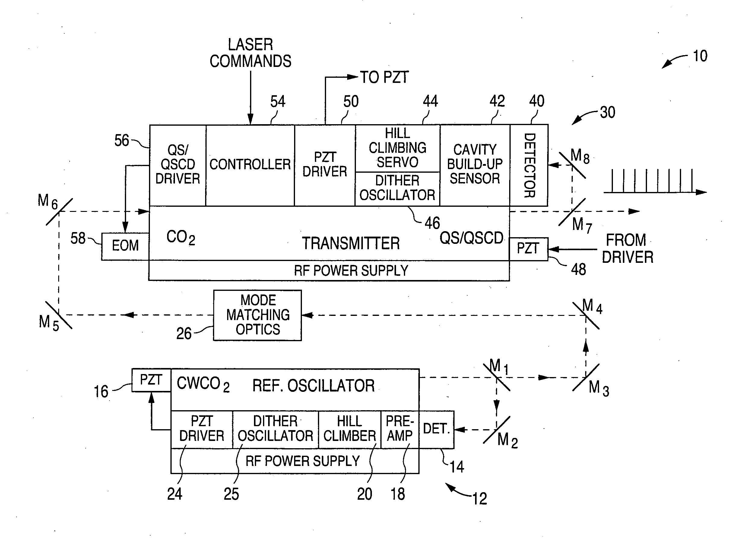
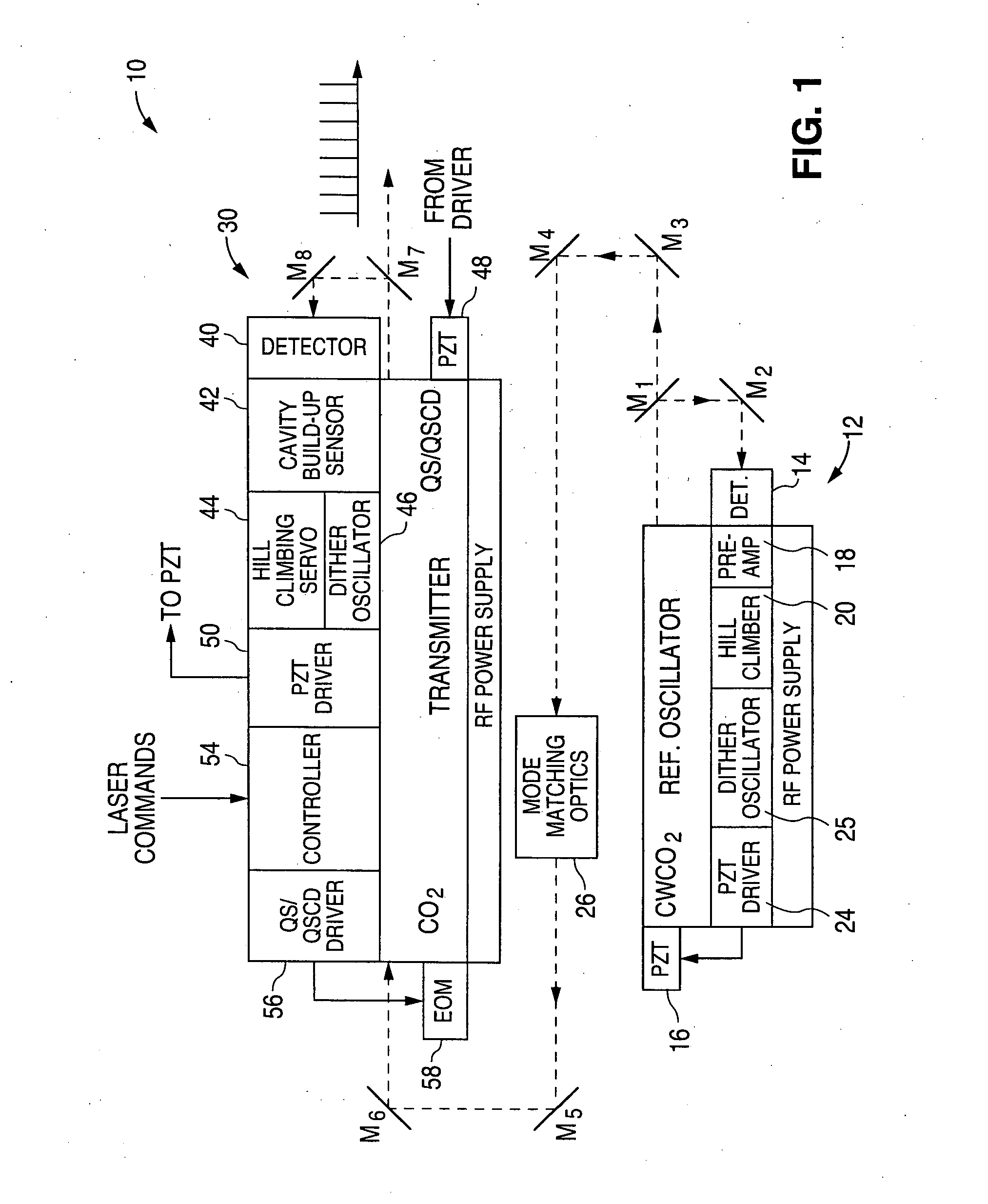
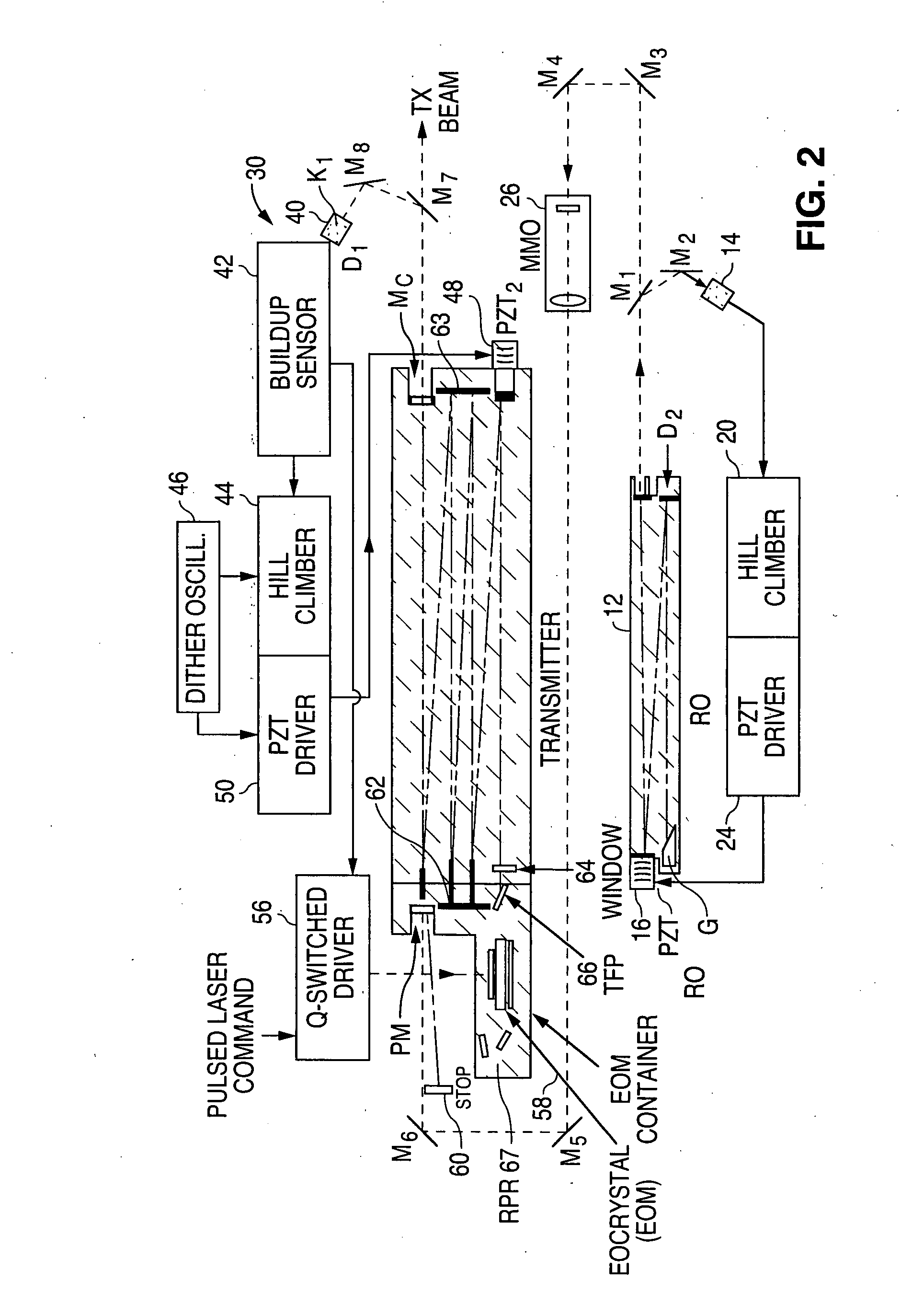
[0017] Systems and methods in accordance with embodiments of the present invention can overcome these and other deficiencies in existing laser systems. Although the embodiments herein will be described with respect to CO2 laser systems, it should be understood that advantages and teachings included herein can be applied equally as well to other QS and / or QSCD lasers, such as solid state lasers.

[0018] Systems in accordance with various embodiments can utilize a CO2 laser reference oscillator (RO) that uses one of a number of well known techniques to lock the output of the RO laser frequency to the peak of the laser line. This locking can be done in one embodiment through the use of appropriate electronics to drive a PZT transducer on which one of the laser mirrors is mounted. The laser line of the RO can be selected by an intercavity optical grating or by using wavelength selective thin film coatings on the resonator mirrors. A grating is particularly desirable if the wavelength to ...


PUM


Abstract

A CO2 laser reference oscillator (RO) can provide injection seeding to a Q-switched (QS) or Q-switched cavity dumped (QSCD) CO2 laser, where the output frequency of the RO laser is locked to the peak of the laser line by the use of appropriate electronics to dither one of the resonator mirrors of the reference oscillator. This injected radiation seeds the radiation building up within the Q-switched laser cavity, such that the oscillating frequency favors the wavelength of the injected radiation. An electronic feedback control circuit can be used to lock an axial mode of the Q-switched laser to line center. The change in build-up time of the pulses within the QS laser can be used to maintain cavity length at a value that enables oscillating at the peak of the same laser line that is injected into QS laser.

Description

[0001] This application claims priority to U.S. Provisional Patent Application Ser. No. 60 / 727,656 filed Oct. 18, 2005, which is incorporated herein by reference.BACKGROUND [0002] Suppliers of photolithographic equipment for the semiconductor industry are actively performing research and development programs directed toward the use of Q-switched (QS) or Q-switched cavity dumped (QSCD) CO2 laser oscillator / amplifier systems for use as the optical pump source in the generation of extreme ultra-violet (EUV) radiation via plasma generation. This course of action has been selected because these lasers have a high peak power output, such as equal to or greater than 1 KW for Q-switched (QS) lasers and about 10 KW for Q-Switched Cavity Dump (QSCD) lasers. These lasers have short pulse durations, such as 0.1 to 2 microseconds for QS lasers and 10 to 30 ns for QSCD lasers. These lasers also have reasonable oscillator output average powers, such as on the order of about 20 to 50 W, in single m...

Claims


Application Information

Patent Timeline
IPC IPC(8): H01S3/08
CPCH01S3/005H01S3/10015H01S3/10092H01S3/115H01S3/134H01S3/1398H01S3/2232
Inventor HENSCHKE, ROBERTFONTANELLA, JOELDEMARIA, ANTHONY J.
Owner COHERENT INC
Why Eureka
Try Eureka