Method and system for forming periodic pulse patterns

a technology of periodic pulse pattern and ultrashot pulse laser, which is applied in the direction of manufacturing tools, instruments, cladded optical fibres, etc., can solve the problems of reducing the stability of machining

Inactive Publication Date: 2007-04-26
RES & INDAL COOPERATION GROUP
View PDF3 Cites 56 Cited by
  • Summary
  • Abstract
  • Description
  • Claims
  • Application Information

AI Technical Summary

Problems solved by technology

However, in fabrication of optical devices such as an optical waveguide, in particular, Bragg grating through irradiation of successive pulse train, a conventional direct-writing technique utilizing a femtosecond laser requires a long processing time to individually scan several thousands of patterns one at a time in order to pattern the glass, and results in reduction of machining stability owing to the long machining time.

Method used


Image

  • Method and system for forming periodic pulse patterns
  • Method and system for forming periodic pulse patterns
  • Method and system for forming periodic pulse patterns

Examples


second embodiment

[0050] The operation of the second embodiment will be explained with reference to FIGS. 5 to 8 as follows.

first embodiment

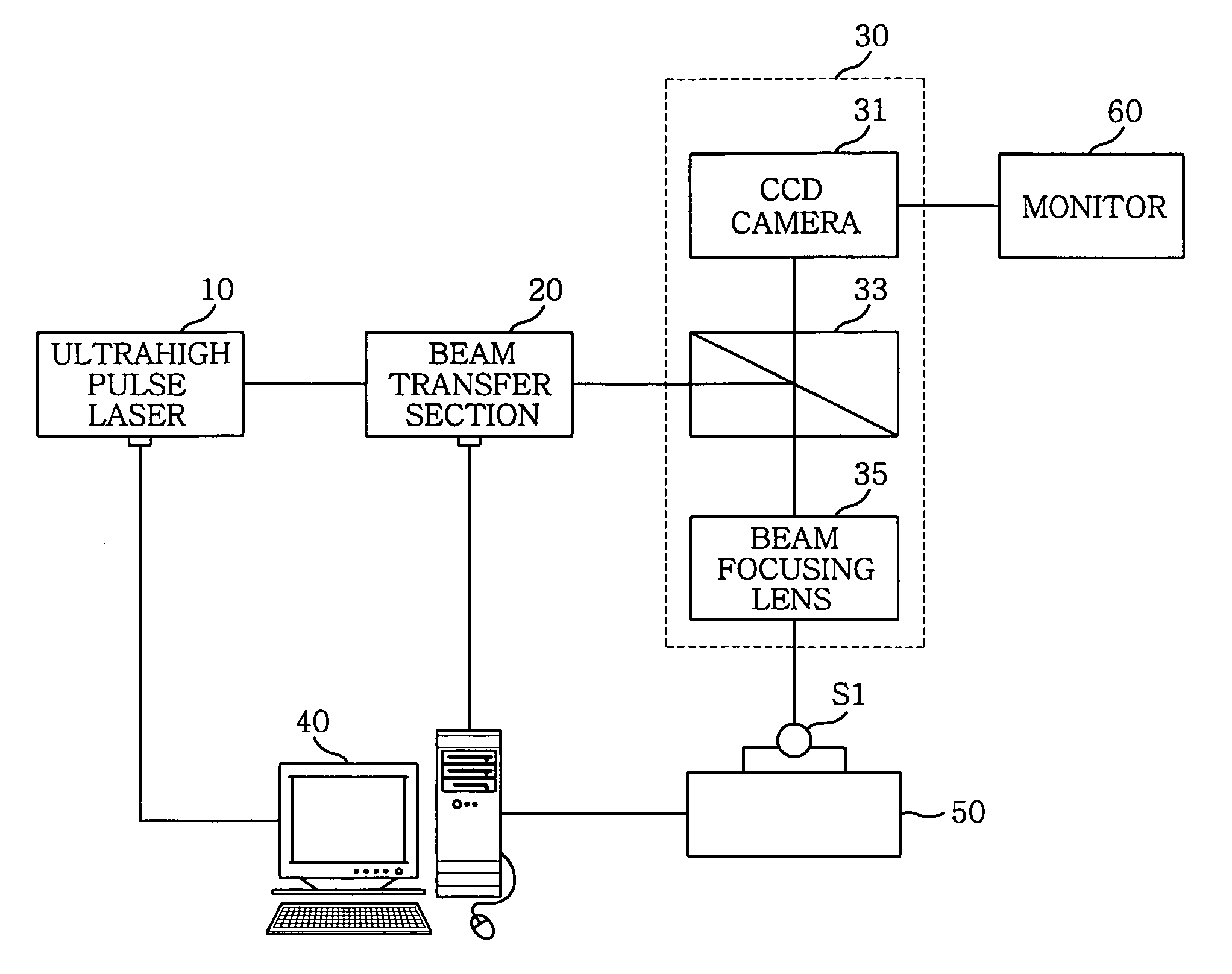
[0051] As similar as the present invention, an ultrashot pulse laser 10 generates an ultrashot pulse laser beam, which will then be transmitted through the beam delivery section 20 to the slit 25.

[0052] The slit 25 is used to provide a line pattern and a size of the slit 25 ranges from 0.5 to 1 mm. The laser beam is changed into a slit beam passing through the slit 25. The slit beam is provided to an optical mirror array 30.

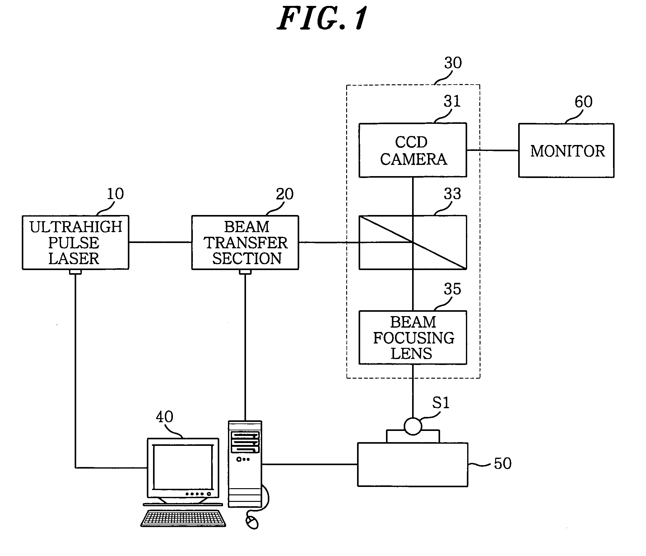
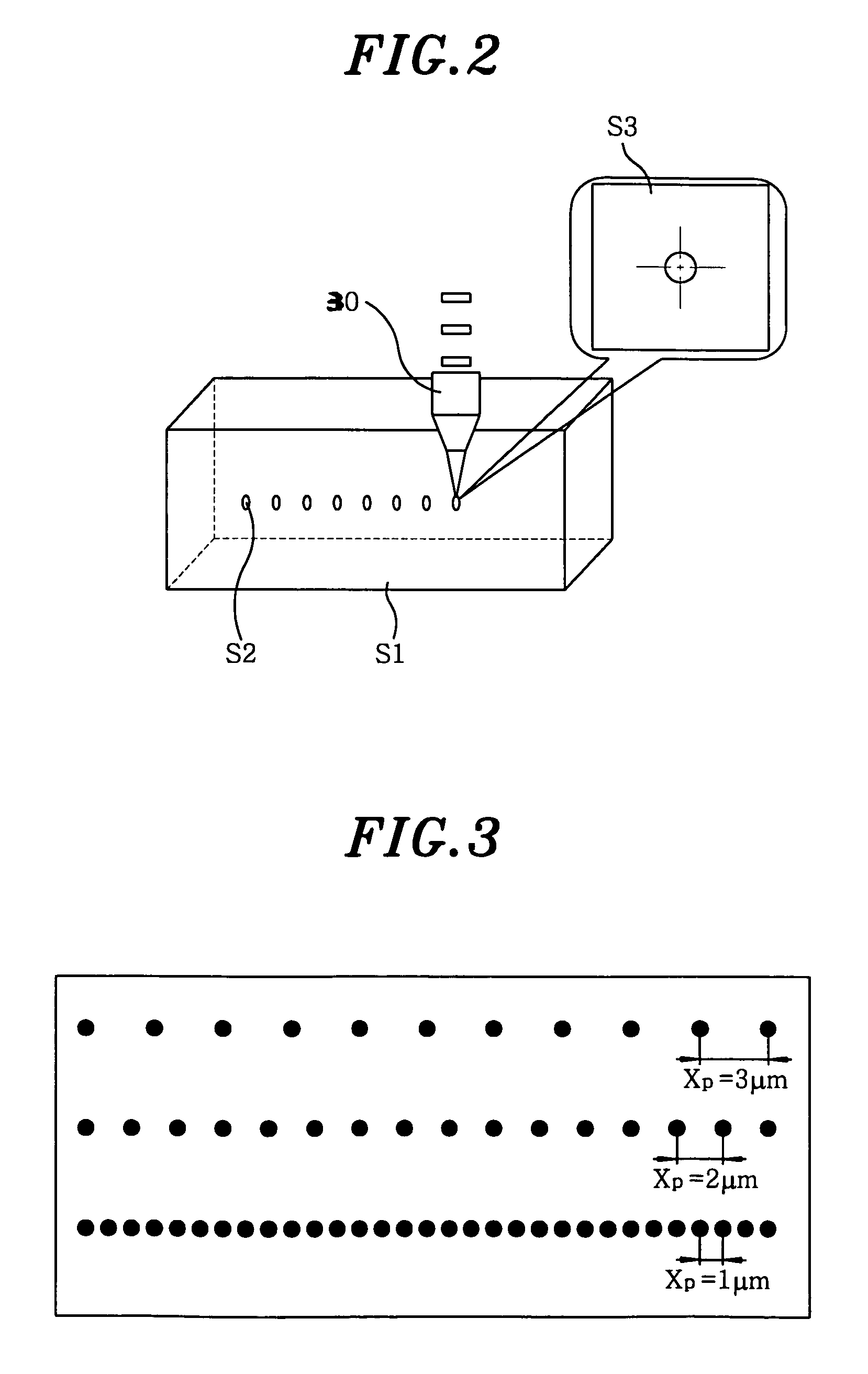
[0053] In the optical mirror array 30, a beam splitter 33 transmits the slit beam to the beam focusing lens 35. The beam focusing lens 35 focuses the slit beam Figto irradiates a line shaped beam SS3 shown in FIG. 6 toward the sample S1. Accordingly, a line pattern SS2 is then formed in the sample S1. Here, the size, width and depth of each line pattern SS2 is properly changed, as shown in FIG. 7, through adjusting the magnification of the beam focusing lens 35, the power density of the ultrashot pulse laser beam from the ultrashot pulse laser 10, and the gap of...


PUM

PropertyMeasurementUnit
wavelengthaaaaaaaaaa
movement speedaaaaaaaaaa

Abstract

A system for forming a periodic pulse pattern in a sample includes a movable stage having the sample loaded thereon, a pulse laser for generating a laser beam of pulses, an objective lens for focusing the laser beam to the sample to form a pattern of pulses in the sample, and a controller for adjusting the movement speed of the movable stage to set a period of the pulse pattern. The pulse pattern includes a spot pattern or a line pattern made by a slit provided between the pulse laser and the objective lens.

Description

FIELD OF THE INVENTION [0001] The present invention relates to a method and a system of forming patterns using an ultrashot pulse laser, and more particularly, to a method and system of forming a periodic pulse pattern of a spot or a line using an ultrashot pulse laser in manufacturing band-gap structured Bragg gratings. BACKGROUND OF THE INVENTION [0002] As is known in the art, optical devices such as an optical waveguide and Bragg grating are widely applied in long-distance communications. The optical waveguide is used to transmit a large amount of optical information over a long distance with low signal attenuation through a core having a relatively high refractive index, which is surrounded by a clad having a low refractive index. The Bragg grating acts as a band limitation filter for separating light beams of a particular wavelength band, and is utilized for a wide variety of applications such as a reflector, a wavelength stabilization device for a laser disc, an optical fiber ...

Claims


Application Information

Patent Timeline
Patent Type & Authority Applications(United States)
IPC IPC(8): H01S3/00G02B6/00B23K26/00B23K26/06G02B6/02G02B6/10G02B6/12
CPCB23K26/0635G02B6/02147G02B2006/1213B23K26/0087B23K26/0045B23K26/0009B23K26/0036B23K26/0039B23K26/0006B23K26/0624B23K26/359B23K2103/42B23K2103/50B23K2103/52G02B6/00G02B6/02
Inventor SOHN, IK BULEE, MAN SEOP
Owner RES & INDAL COOPERATION GROUP
Why Eureka
Try Eureka