X-ray filter having dynamically displaceable x-ray attenuating fluid

a filter and dynamic technology, applied in the field of radiographic imaging, can solve the problems of inability to provide independent data or feedback as to the energy and incident flux rate of photons, inability to provide energy discriminatory data or otherwise count the number and/or measure the energy of photons actually received by a given detector element or pixel, and inability to provide ct imaging as a viable diagnostic imaging tool, etc., to achieve low x-ray flux, low x-ray flux, saturation edge edge array

a filter and dynamic technology, applied in the field of radiographic imaging, can solve the problems of inability to provide independent data or feedback as to the energy and incident flux rate of photons, inability to provide energy discriminatory data or otherwise count the number and/or measure the energy of photons actually received by a given detector element or pixel, and inability to provide ct imaging as a viable diagnostic imaging tool, etc., to achieve low x-ray flux, low x-ray flux, saturation edge edge array

US20070092066A1Inactive Publication Date: 2007-04-26GENERAL ELECTRIC CO

Image

  • X-ray filter having dynamically displaceable x-ray attenuating fluid
  • X-ray filter having dynamically displaceable x-ray attenuating fluid
  • X-ray filter having dynamically displaceable x-ray attenuating fluid

Examples


Embodiment Construction

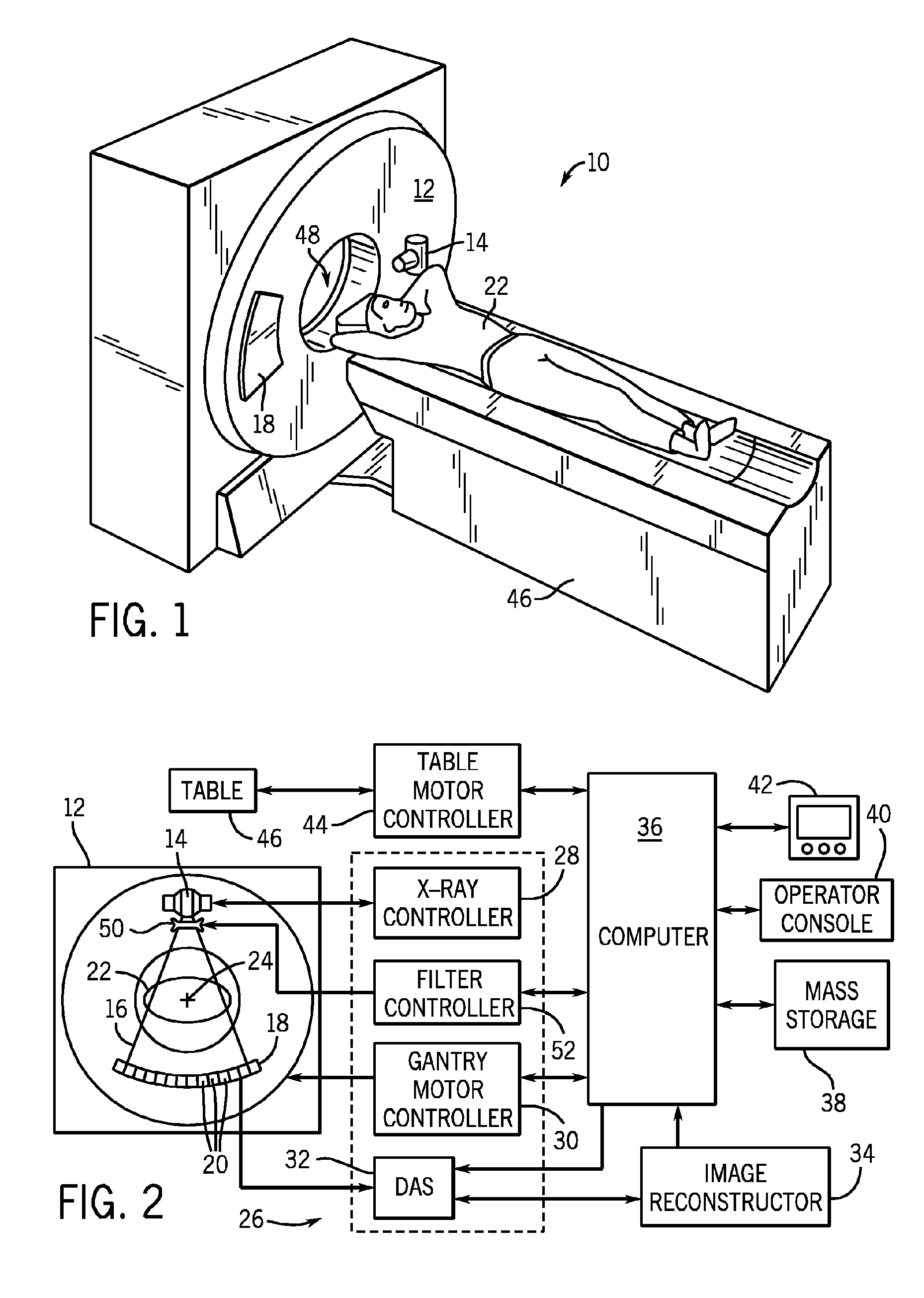
[0033] The operating environment of the present invention is described with respect to a four-slice computed tomography (CT) system. However, it will be appreciated by those skilled in the art that the present invention is equally applicable for use with single-slice or other multi-slice configurations. Moreover, the present invention will be described with respect to the detection and conversion of x-rays. However, one skilled in the art will further appreciate that the present invention is equally applicable for the detection and conversion of other high frequency electromagnetic energy.

[0034] While the present invention is applicable with a number of radiographic imaging systems, it is particularly well-suited for CT systems and, especially, those systems having detectors with relative small dynamic range, such as photon counting and energy discriminating detectors. In this regard, the present invention is believed to be a key enabler for the use of direct conversion and energy ...


PUM


Abstract

A bowtie filter is constructed to have a fluidic envelope filled with attenuating fluid and a displacement insert that can present various x-ray attenuation profiles during a scan. The insert is designed to displace the attenuating fluid to achieve a denied attenuating or filtering profile. The insert can be rotated, twisted, moved, and otherwise contorted within the fluidic envelope as needed during the course of a scan. As the angle, position and shape of the zombie is changed, the x-ray profile of the filter changes. The insert may have a default shape when at rest, but can have its shape changed when external forces are placed thereon. As x-ray filtering needs change during the course of the scan, the insert can be compressed, stretched, and / or contorted to achieve additional filtering profiles.

Description

BACKGROUND OF THE INVENTION [0001] The present invention relates generally to radiographic imaging and, more particularly, to an x-ray filter having dynamically displaceable x-ray attenuating fluid. [0002] Typically, in radiographic systems, an x-ray source emits x-rays toward a subject or object, such as a patient or a piece of luggage. Hereinafter, the terms “subject” and “object” may be interchangeably used to describe anything capable of being imaged. The x-ray beam, after being attenuated by the subject, impinges upon an array of radiation detectors. The intensity of the radiation beam received at the detector array is typically dependent upon the attenuation of the x-rays through the scanned object. Each detector element of the detector array produces a separate signal indicative of the attenuated beam received by each detector element. The signals are transmitted to a data processing system for analysis and further processing which ultimately produces an image. Generally, the...

Claims


Application Information

Patent Timeline
26 Apr 2007
Publication
US20070092066A1
IPC
G21K3/00
CPC
G21K1/10
Inventors
TKACZYK, J. ERIC; WALTER, DEBORAH J.