
Signal processing device and sound image orientation apparatus

Inactive Publication Date: 2007-04-26
YAMAHA CORP
View PDF7 Cites 20 Cited by
  • Summary
  • Abstract
  • Description
  • Claims
  • Application Information

AI Technical Summary

Benefits of technology

[0013] Thus, it is an object of the present invention to provide a sound image orientation apparatus solving a problem that a tone quality is unnatural and sound may be sometimes hardly heard due to a personal difference or a deviation from a position supposed to be effected by a model head transfer function.
[0019] For instance, when not a headphone, but a floor speaker is used, the virtual characteristic giving filter having the structure described in (1) is supposed to pass through the cross-talk cancel filter. According to the present invention, in the sound image orientation apparatus passing through the cross-talk cancel filter, the effects of (1) can be achieved. That is, in the present invention, according to the structure described in (1), since the dip part can be adjusted by the adjusting unit, not only a problem that the tone quality is unnatural is solved, but also the effect of a sound image orientation can be adequately exhibited to meet an individual head transfer function or a deviation from a supposed position.
[0020] According to the present invention, not only a problem that the tone quality is unnatural is solved, but also an adequate sound image orientation can be realized to meet an individual head transfer function or a deviation from a supposed position.

Problems solved by technology

When the dip is deleted in such a way, a sound orientation is insufficient.
Thus, not only a problem that the tone quality is unnatural is solved, but also such a signal processing operation as to realize an adequate sound image orientation can be carried out to meet an individual head transfer function or a deviation from a supposed position.

Method used


Image

  • Signal processing device and sound image orientation apparatus
  • Signal processing device and sound image orientation apparatus
  • Signal processing device and sound image orientation apparatus

Examples


Embodiment Construction

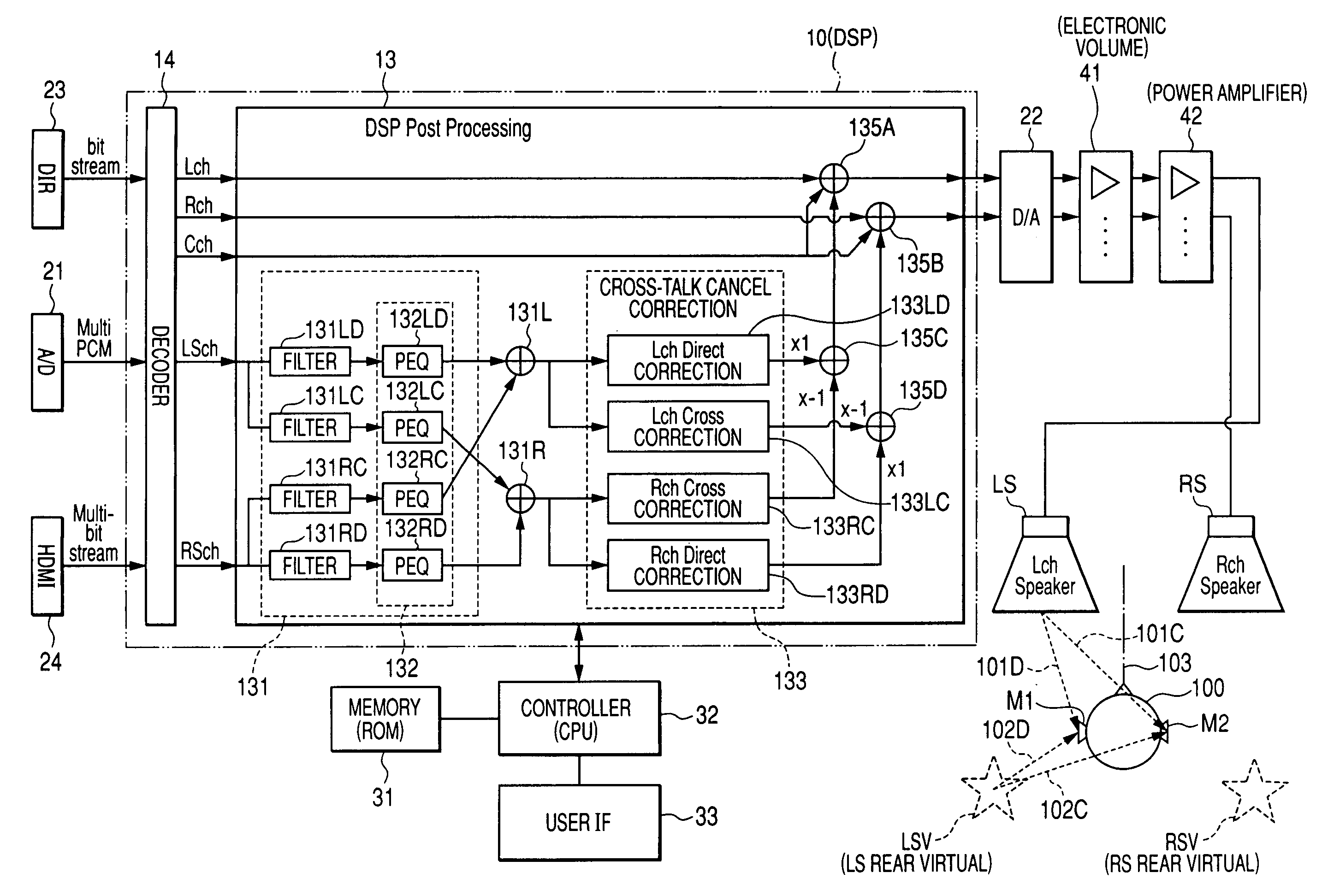
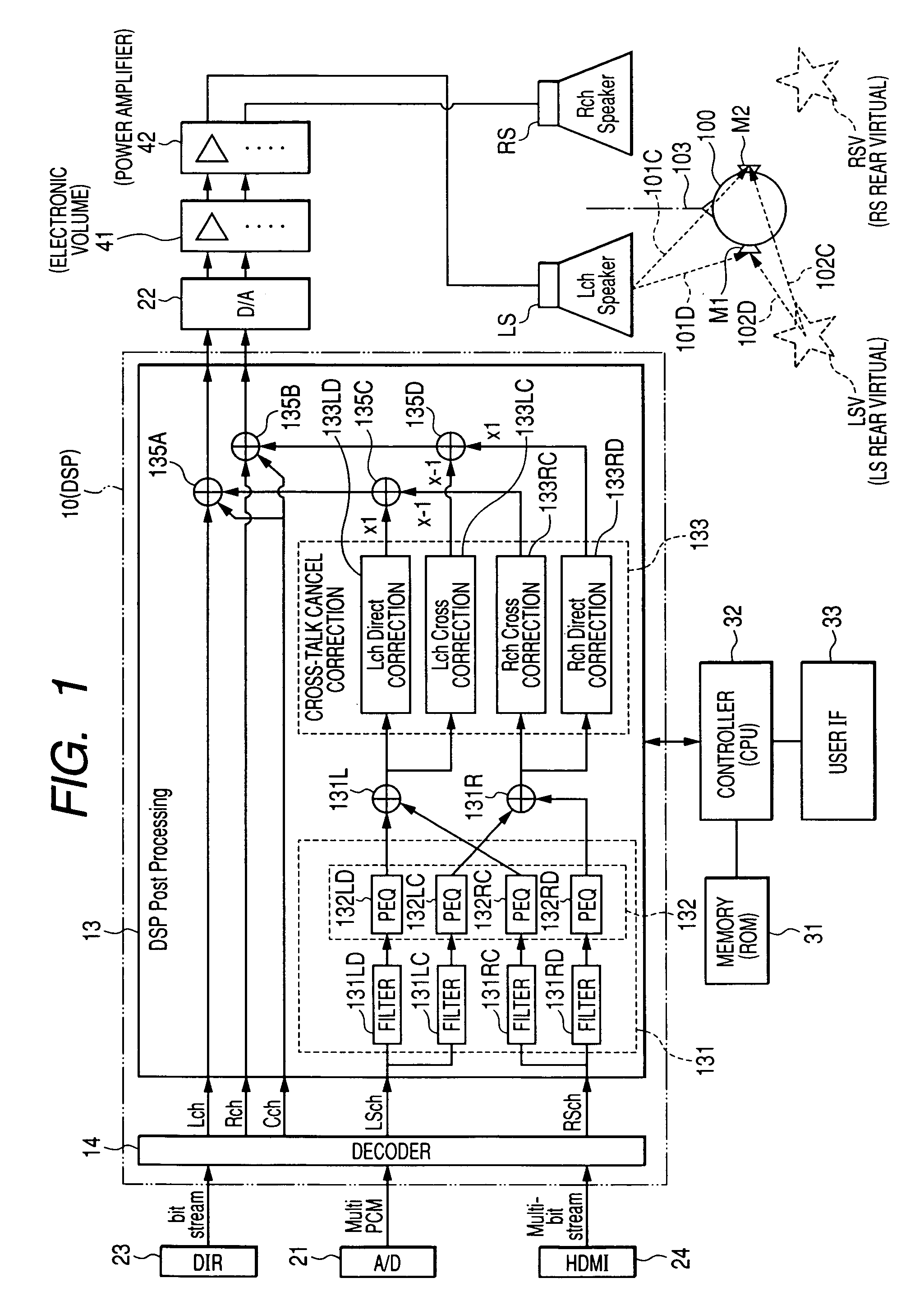
[0026] Now, a sound image orientation apparatus of this embodiment will be described below by referring to FIG. 1. FIG. 1 shows the structure of the sound image orientation apparatus according this embodiment during a reproduction thereof.

[0027] A summary of the structure of the sound image orientation apparatus will be briefly described below. Namely, a digital sound signal of input parts 23, 21, and 24 is fetched and the signal is digitally processed by a DSP 10. The digital sound signal is converted into an analog sound signal by a D / A converter 22. A sound volume is adjusted by an electronic volume 41. The analog sound signal is outputted to an Lch speaker LS and an Rch speaker RS by a power amplifier 42 to generate a sound.

[0028] Further, the summary of a function of the sound image orientation apparatus of this embodiment will be described in a single word. Sound signals of 5 ch including an Lch, an Rch, a Cch, an LSch and an RSch as shown in FIG. 1 are mixed down to create ...


PUM


Abstract

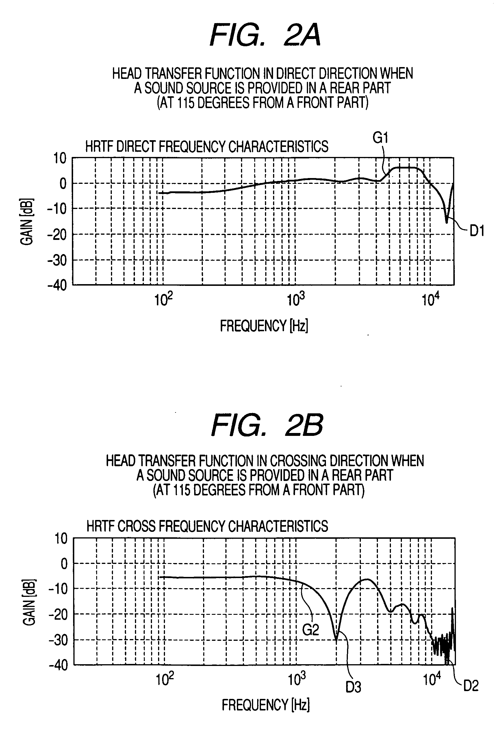
A signal processing device includes a filter that is set to frequency characteristics in which a dip existing in an intermediate and high frequency range is smoothed in the frequency characteristics of a virtual characteristic applying filter for applying transfer characteristics of a space transfer path to a sound signal, the space transfer path extending from a virtually set orientation of a sound image to an ear of a listener, an equalizer that forms the dip by cutting a part of the intermediate and high frequency range, and an adjusting unit that adjusts at least a central frequency of the dip. An input signal is passed through the filter and the equalizer.

Description

BACKGROUND OF THE INVENTION [0001] The present invention relates to a sound image orientation apparatus having a cross-talk cancel and correcting function and forming a sound field on the basis thereon. [0002] Usually, a spatial propagation from a virtual sound source to the ear of a listener is modeled to add such an acoustic effect to which the virtual sound source is oriented (for instance, see Patent Documents 1 to 3). [0003] A sound image orientation apparatus having a cross-talk cancel function has been hitherto disclosed (for instance, see, Patent Document 1.). A component reaching from a right speaker to the left ear or vice versa is referred to as a cross-talk and a function for canceling the cross-talk is referred to as a cross-talk cancel. The cross-talk cancel means a technique that enables the left side ear to hear only the sound of a left side speaker and the right side ear to hear only the sound of the right side speaker and eliminates the orientation of the speakers ...

Claims


Application Information

Patent Timeline
IPC IPC(8): H04R5/00H04R5/02
CPCH04S7/307H04S2400/01H04S2420/01
Inventor KATAYAMA, MASAKITAKESHITA, KENICHIROMASUDA, KATSUHIKO
Owner YAMAHA CORP
Learn More