Method and apparatus for controlling material vibration modes in polymer and paper high performance speaker diaphragms

a polymer and paper technology, applied in the direction of diaphragm construction, transducer diaphragm, electromechanical transducer, etc., can solve the problems of non-uniform velocity displacement of the diaphragm, non-linear acoustic output at varying frequencies, and the poor acoustic quality of the radiated sound of the loudspeaker transducer made with the above stiffening approach

Inactive Publication Date: 2007-04-26
MCKENZIE MARK DOUGLAS
View PDF13 Cites 7 Cited by
  • Summary
  • Abstract
  • Description
  • Claims
  • Application Information

AI Technical Summary

Benefits of technology

[0009] The present invention relates to electrodynamic loudspeaker transducer diaphragms, and more particularly to a loudspeaker transducer diaphragm having a good quality of acoustic output uncontaminated by acoustic output additions from diaphragm material vibration modes.

Problems solved by technology

The cone vibration modes result in non-uniform velocity displacement of the diaphragm and deviation from the ideal of piston-like behavior of the diaphragm 10.
The non-uniform velocity displacement causes peaks and valleys in the frequency response of the loudspeaker transducer resulting in non-linear acoustic output at varying frequencies.
Loudspeaker transducers made with the aforementioned stiffening approaches can still suffer from poor acoustical quality of the radiated sound due to contamination by diaphragm material vibration modes as shown in FIGS. 6, 9, 11, and 13.

Method used


Image

  • Method and apparatus for controlling material vibration modes in polymer and paper high performance speaker diaphragms
  • Method and apparatus for controlling material vibration modes in polymer and paper high performance speaker diaphragms
  • Method and apparatus for controlling material vibration modes in polymer and paper high performance speaker diaphragms

Examples


second embodiment

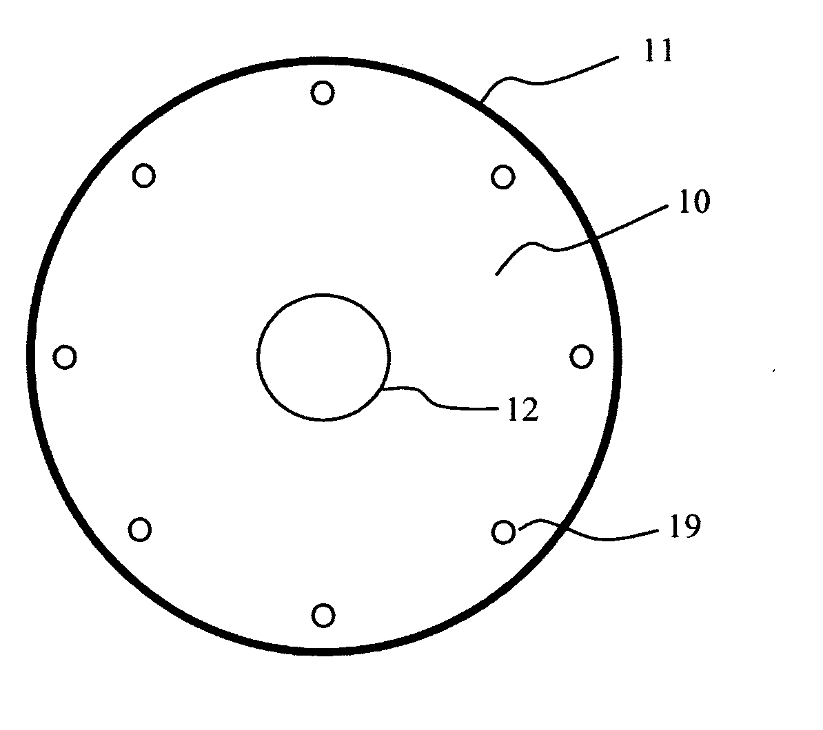
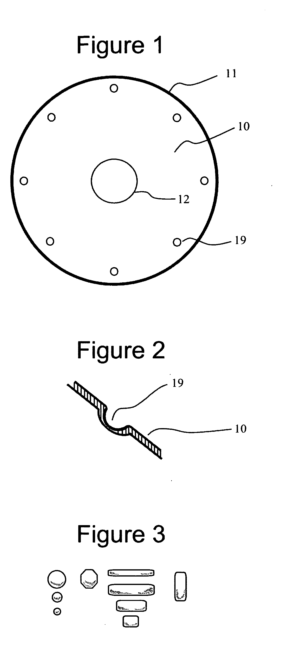
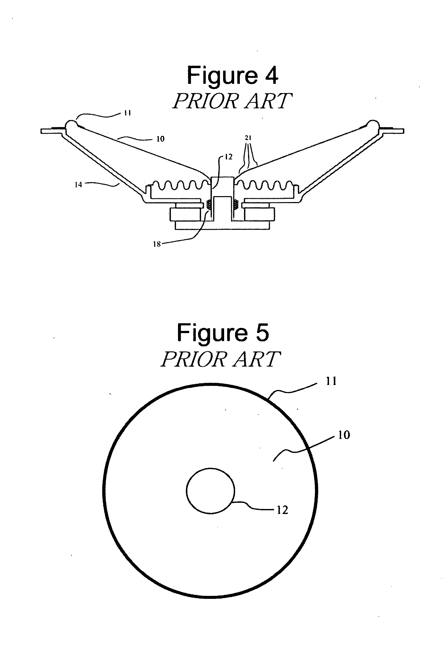
[0041] A second embodiment of the invention is intended for transducer diaphragm 10 wherein the diaphragm material is formed paper sheet or pulp paper materials. Here the invention is applied to the paper diaphragm loudspeaker transducer of FIGS. 4 and 5. The frequency response of the loudspeaker transducer of FIG. 4 and 5 is shown in FIG. 6. The dimpling pattern to control the five kHz center frequency diaphragm material vibration mode is shown in FIG. 20. As in the preferred embodiment, the second embodiment utilizes the dimple shape of the preferred embodiment.

[0042] In the second embodiment, eight cold die dimples are impressed in the cone. The dimples have the cross-sectional shape shown in FIG. 2. In the second embodiment, the dimples alter the mechanical impedance of the dimpled area of the diaphragm material by displacing the location of paper fibers and disrupting adhesions amongst the paper fibers in the dimpled areas of the material.

[0043] The control provided by the ei...


PUM


Abstract

A method for reducing the radiation amplitude of material vibration modes (division vibrations) from a loudspeaker transducer diaphragm mechanically vibrated for the purpose of transforming an electrical signal into an acoustic signal. The diaphragm material may consist of formed paper or plastic sheet materials or molded paper pulp. The amplitude reduction of material vibration modes and pressure waves within the diaphragm material is accomplished by impressing small, shaped structures within the diaphragm material at critical locations determined by measurement with laser vibration analysis or position sensitive transient analysis of a loudspeaker transducer. The method is applied to the diaphragm material after it has been formed into the shape of a loudspeaker transducer diaphragm, either before or after the diaphragm has been assembled into a loudspeaker transducer.

Description

CROSS-REFERENCE TO RELATED APPLICATIONS [0001] This application claims the benefit of U.S. Provisional Application No. 60 / 729,982, filed Oct. 25, 2005, entitled “Method and Apparatus for Controlling Material Vibration Modes in Polymer High Performance Speaker Diaphragms;” U.S. patent application Ser. No. 11 / 477,027, filed Jun. 27, 2006, entitled “Boundary Layer Regulator for Extended Range Acoustical Transducers.”STATEMENT REGARDING FEDERALLY SPONSORED RESEARCH OR DEVELOPMENT [0002] Not Applicable REFERENCE TO SEQUENCE LISTING, A TABLE, OR A COMPUTER PROGRAM LISTING COMPACT DISC APPENDIX [0003] Not Applicable BACKGROUND OF THE INVENTION [0004] The sound quality of loudspeaker transducers have been limited by unintended diaphragm material vibration modes also know as diaphragm breakup, diaphragm resonances, diaphragm ringing, modal behavior patterns, or divisional vibrations. Diaphragm material vibration modes are chaotic phenomena where diaphragm motions become highly complex and wh...

Claims


Application Information

Patent Timeline
Patent Type & Authority Applications(United States)
IPC IPC(8): H04R9/06
CPCH04R7/122H04R7/14H04R9/06H04R2307/021H04R2307/025H04R2307/029
Inventor MCKENZIE, MARK DOUGLAS
Owner MCKENZIE MARK DOUGLAS
Why Eureka
Try Eureka