System And Method For Reducing Backlash In A Planetary Gear Set

a technology of planetary gear set and backlash reduction, applied in the field of systems and methods for controlling gear rattle, can solve the problems of increased noise, unacceptable amount of gear rattle during operation, and high internal stress, and achieve the effect of reducing or eliminating the backlash to control gear rattle, reducing or eliminating the effective backlash of gear

Inactive Publication Date: 2007-04-26
FORD GLOBAL TECH LLC
View PDF9 Cites 23 Cited by
  • Summary
  • Abstract
  • Description
  • Claims
  • Application Information

AI Technical Summary

Benefits of technology

[0007] The present invention provides systems and methods for reducing or eliminating backlash to control gear rattle that include a planetary gear set with a planet carrier including a first part that supports at least one forward-torque carrying planet gear that contacts the drive side of at least one tooth of both an associated sun gear and ring gear, and a second part that supports at least one reverse-torque carrying planet gear that contacts the coast side of gear teeth of the associated sun gear and ring gear, the second part of the carrier being rotationally biased with a spring preload relative to the first part to reduce or eliminate effective backlash of the gear set.
[0008] In one embodiment, the first and second parts of the planet carrier are spring loaded relative to each other. One or more springs are disposed between the first and second parts at approximately the middle of the face width of the teeth of the planet pinion gears mounted on the planet carrier. A plurality of planet pinion gears are mounted on the first part of the planet carrier, which is held stationary, and as many planet pinion gears are mounted on the moveable second part of the planet carrier. The gear teeth of planet pinion gears mounted on the stationary first part of the planet carrier maintain contact against the drive sides of the gear teeth on mating gears whereas the gear teeth of planet pinion gears mounted on the second moveable part of the planetary carrier maintain contact with the coast sides of the gear teeth on mating gears. During normal operation, the planet pinion gears mounted to the stationary first part of the planet carrier carry the load of the input torque, as well as the spring preload between the two carriers, while the planet pinion gears mounted to the moveable second part of the planet carrier are loaded not greater than the spring preload between the two parts of the planet carrier. Both the stationary first part and the moveable second part of the planet carrier have a rigid hoop structure at both ends of each of the axle shafts that support the planet gears, with additional structure to attach the hoops of each part to each other. This rigid structure ensures that the gears will maintain proper centerline alignment even when they are carrying a heavy load. The spring preload between the two parts of the carrier assembly should be at least as large as the maximum load that will be imposed in the reverse direction during operation of the gear set for most advantageous operation. This type of construction provides essentially zero backlash in all angular positions under normal operating conditions without forcing mating gear teeth to be in a tight, noncompliant mesh condition. In addition, the spring load prevents creation of high stresses due to gear run-out.
[0010] The present invention provides a number of advantages. For example, the present invention provides systems and methods for reducing or eliminating gear rattle by eliminating backlash in a planetary gear set without changing the center distance between gears, gear tooth thickness, or gear tooth profile. The present invention eliminates backlash using an automatic and dynamic adjustment without requiring any manual adjustment. The present invention does not require external tools to adjust gear position to eliminate backlash after assembly. Eliminating backlash using the present invention does not force the gears into a tight, noncompliant mesh condition due to gear run-out or thermal expansion and therefore does not compromise durability or performance or generate additional gear noise within the planetary gear set. The present invention offers high torsional stiffness in the positive torque transmission direction equivalent to the stiffness of a conventional planetary gear set and also in the direction of backward or reverse torque transmission up to the torque level of the spring preload, which is set to be slightly greater than the anticipated maximum load due to torque in the backward direction. This configuration reduces susceptibility to vibrational resonance when subjected to torsional vibrations at the input or output members.
[0011] The present invention may be used in a number of diverse applications, but is particularly suited for applications that experience torsional vibration and / or torque reversals where a conventional planetary gear set would generate undesirable or unacceptable gear rattle. For example, the present invention may allow variable displacement engines to idle and drive at low engine speeds with fewer than all of the cylinders firing without unacceptable gear rattle. Also, the reduced or eliminated gear rattle should reduce noise, vibration, and harshness (NVH) with the uneven firing intervals that occur when an 8-cylinder engine operates in a reduced or variable displacement mode with 3, 5, or 7 firing cylinders, for example.

Problems solved by technology

Mating gear teeth in a pair of gears have an inherent amount of backlash attributable to clearance required to accommodate manufacturing variation and thermal expansion, which may allow an unacceptable amount of rattle during operation, particularly when experiencing frequent torque reversals between left and right hand (also referred to as clockwise / counter clockwise, positive / negative, drive / coast, or forward / reverse) torques.
Manually adjusting backlash as described in these disclosures may result in additional noise and produce high internal stresses related to gear run-out and an associate tight contact or binding condition during subsequent operation.
The low elasticity in both forward and backward directions could lead to unacceptable vibrational resonance if the input or output is subjected to torsional vibrations.

Method used


Image

  • System And Method For Reducing Backlash In A Planetary Gear Set
  • System And Method For Reducing Backlash In A Planetary Gear Set
  • System And Method For Reducing Backlash In A Planetary Gear Set

Examples


Embodiment Construction

)

[0028] As those of ordinary skill in the art will understand, various features of the present invention as illustrated and described with reference to any one of the Figures may be combined with features illustrated in one or more other Figures to produce embodiments of the present invention that are not explicitly illustrated or described. The combinations of features illustrated provide representative embodiments for typical applications. However, various combinations and modifications of the features consistent with the teachings of the present invention may be desired for particular applications or implementations.

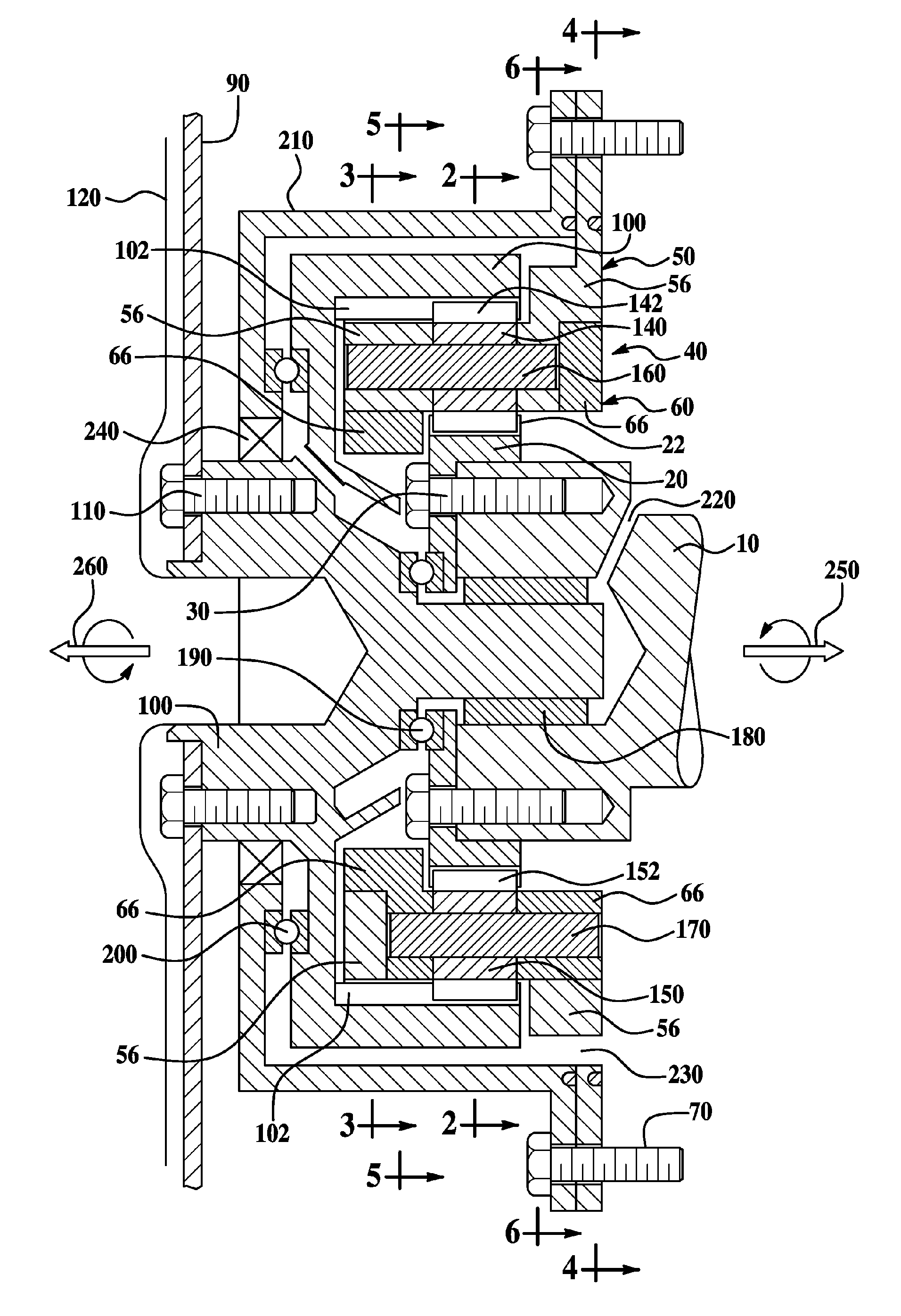
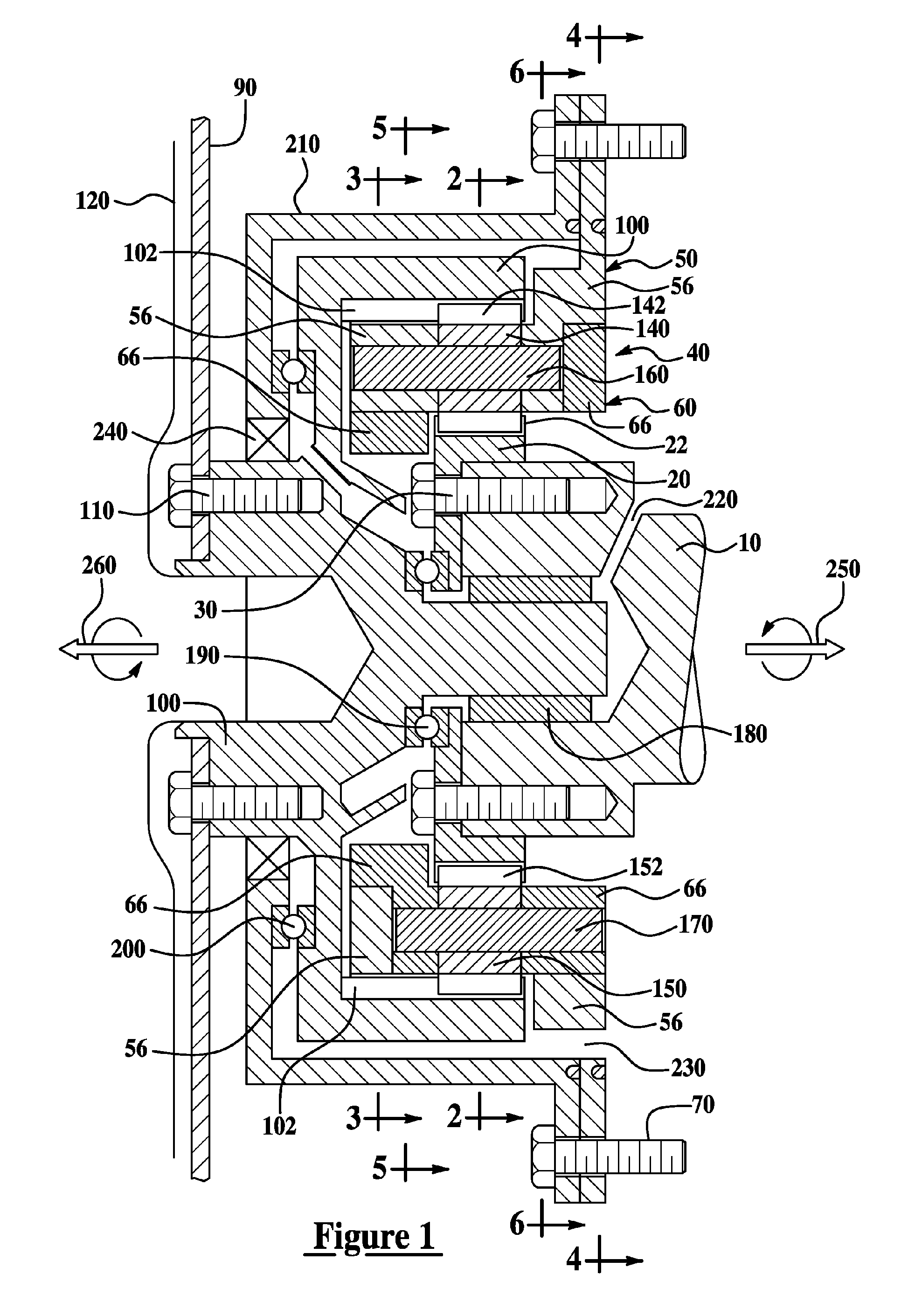
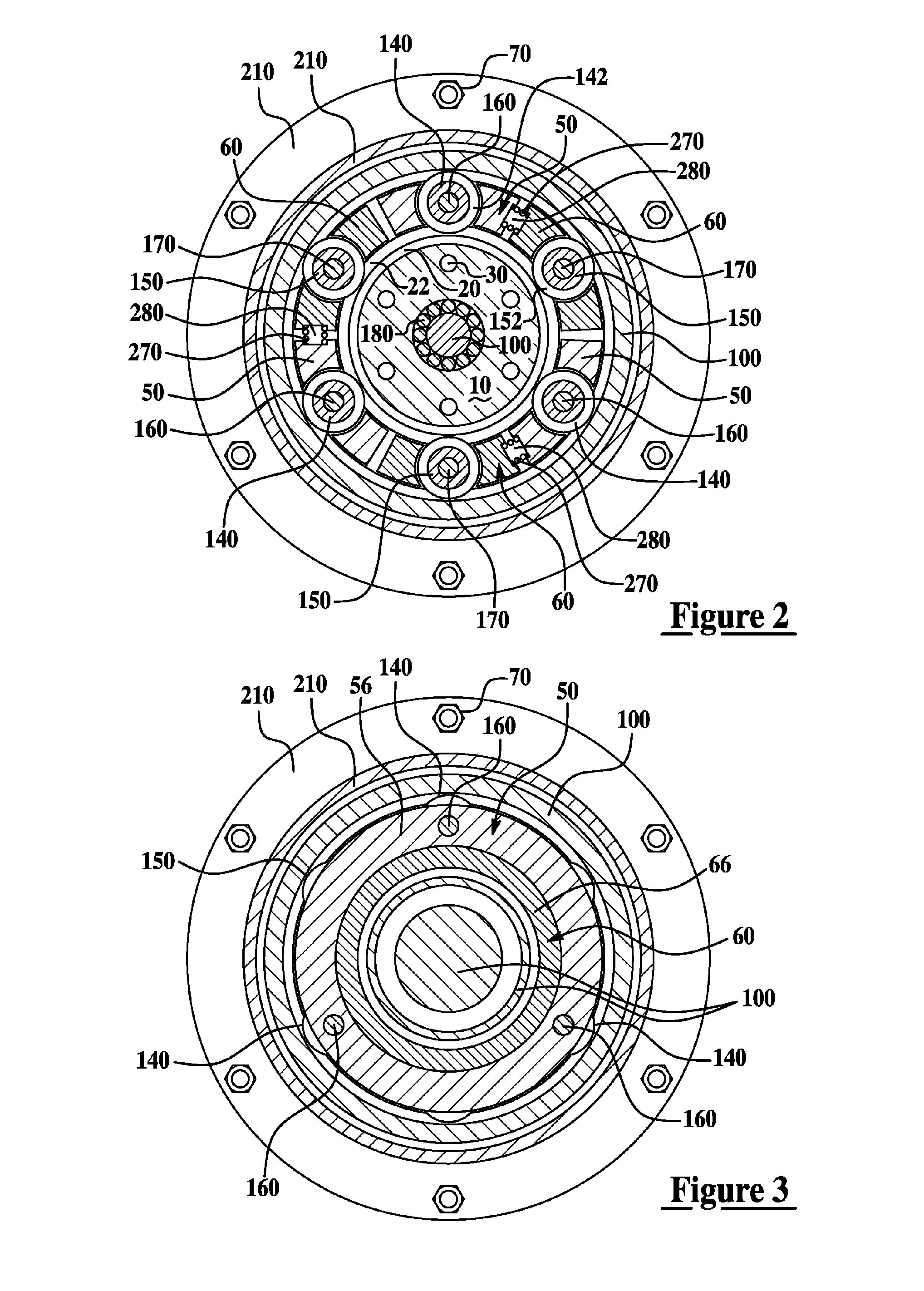
[0029] Referring now to FIG. 1, a side cross-section view of a representative application for a two-part carrier planetary gear set for coupling a drivetrain to an engine in a system or method for eliminating backlash to control gear rattle according to one embodiment of the present invention is shown. In this embodiment, the planetary gear set reverses rotational di...


PUM


Abstract

Systems and methods for reducing or eliminating backlash to control gear rattle include a planetary gear set with a planet carrier including a first part that supports at least one forward-torque carrying planet gear that has at least one tooth contacting a drive side of gear teeth of an associated sun gear and ring gear and a second part that supports at least one reverse-torque carrying gear that has at least one tooth contacting a coast side of gear teeth of the associated sun gear and ring gear, the second part of the carrier being rotationally biased relative to the first part to reduce or eliminate effective backlash of the gear set.

Description

BACKGROUND OF THE INVENTION [0001] 1. Field of the Invention [0002] The present invention relates to systems and methods for controlling gear rattle by substantially eliminating backlash in a planetary gear set. [0003] 2. Background Art [0004] Mating gear teeth in a pair of gears have an inherent amount of backlash attributable to clearance required to accommodate manufacturing variation and thermal expansion, which may allow an unacceptable amount of rattle during operation, particularly when experiencing frequent torque reversals between left and right hand (also referred to as clockwise / counter clockwise, positive / negative, drive / coast, or forward / reverse) torques. Prior art solutions to this problem include reduction or elimination of backlash by varying the center distance between gears or changing tooth thickness. One solution to eliminating backlash in external gears is disclosed in U.S. Pat. No. 4,688,441 in which one of the gears is split axially into two parts that are und...

Claims


Application Information

Patent Timeline
Patent Type & Authority Applications(United States)
IPC IPC(8): F16H57/08
CPCF16H1/2863F16H57/082
Inventor BERGER, AL
Owner FORD GLOBAL TECH LLC
Why Eureka
Try Eureka