

Surgical tool for electrode implantation
a surgical tool and electrode technology, applied in the field of implantable medical devices, can solve the problems of large protruding devices, heavy weight, and inability to produce adequate simulated vision to truly aid the visually impaired, and increase the possibility of retinal trauma
- Summary
- Abstract
- Description
- Claims
- Application Information
AI Technical Summary
Benefits of technology
Problems solved by technology
Method used
Image

Examples
Embodiment Construction
[0035] The following description is of the best mode presently contemplated for carrying out the invention. This description is not to be taken in a limiting sense, but is made merely for the purpose of describing the general principles of the invention. The scope of the invention should be determined with reference to the claims.
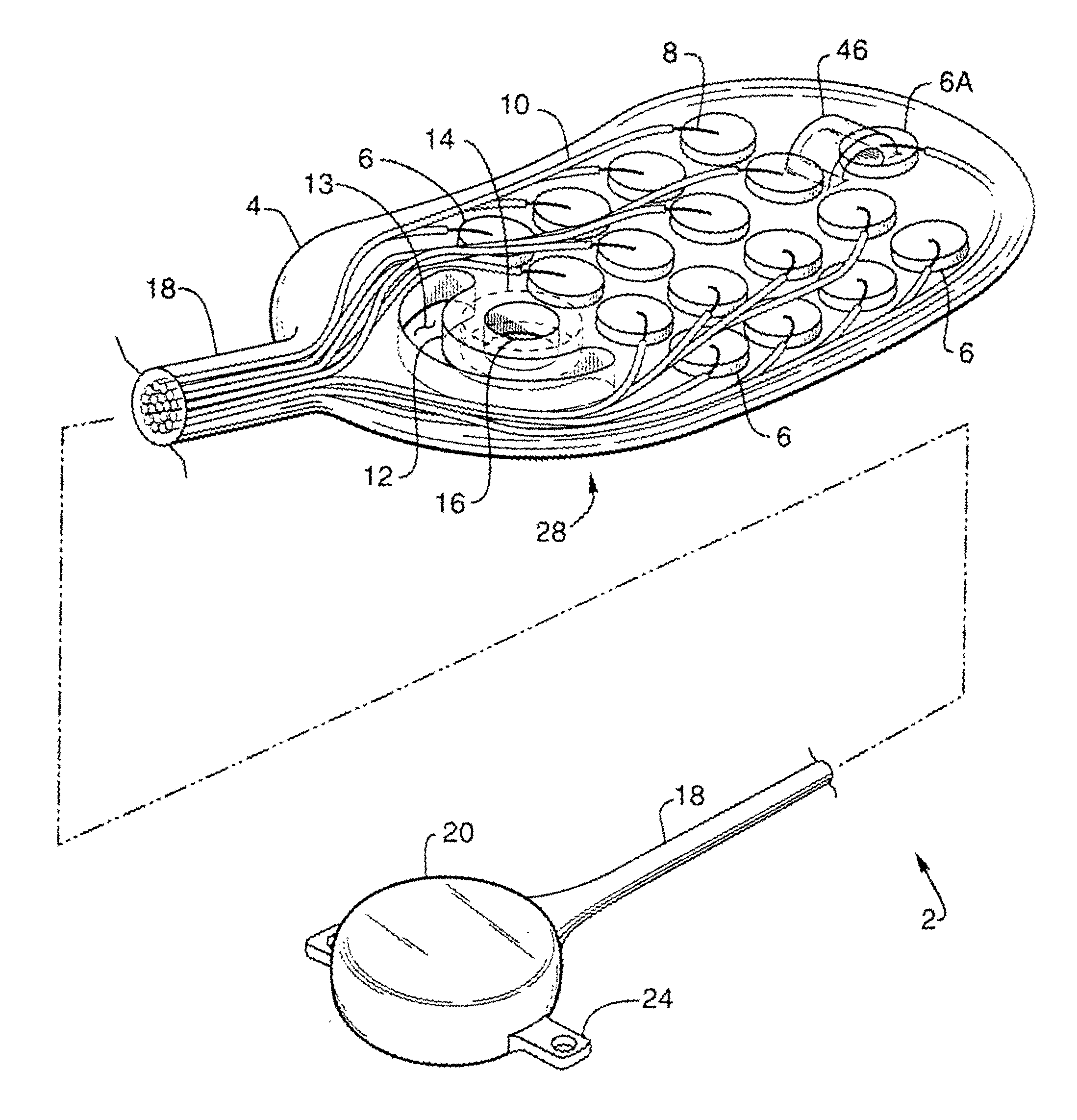
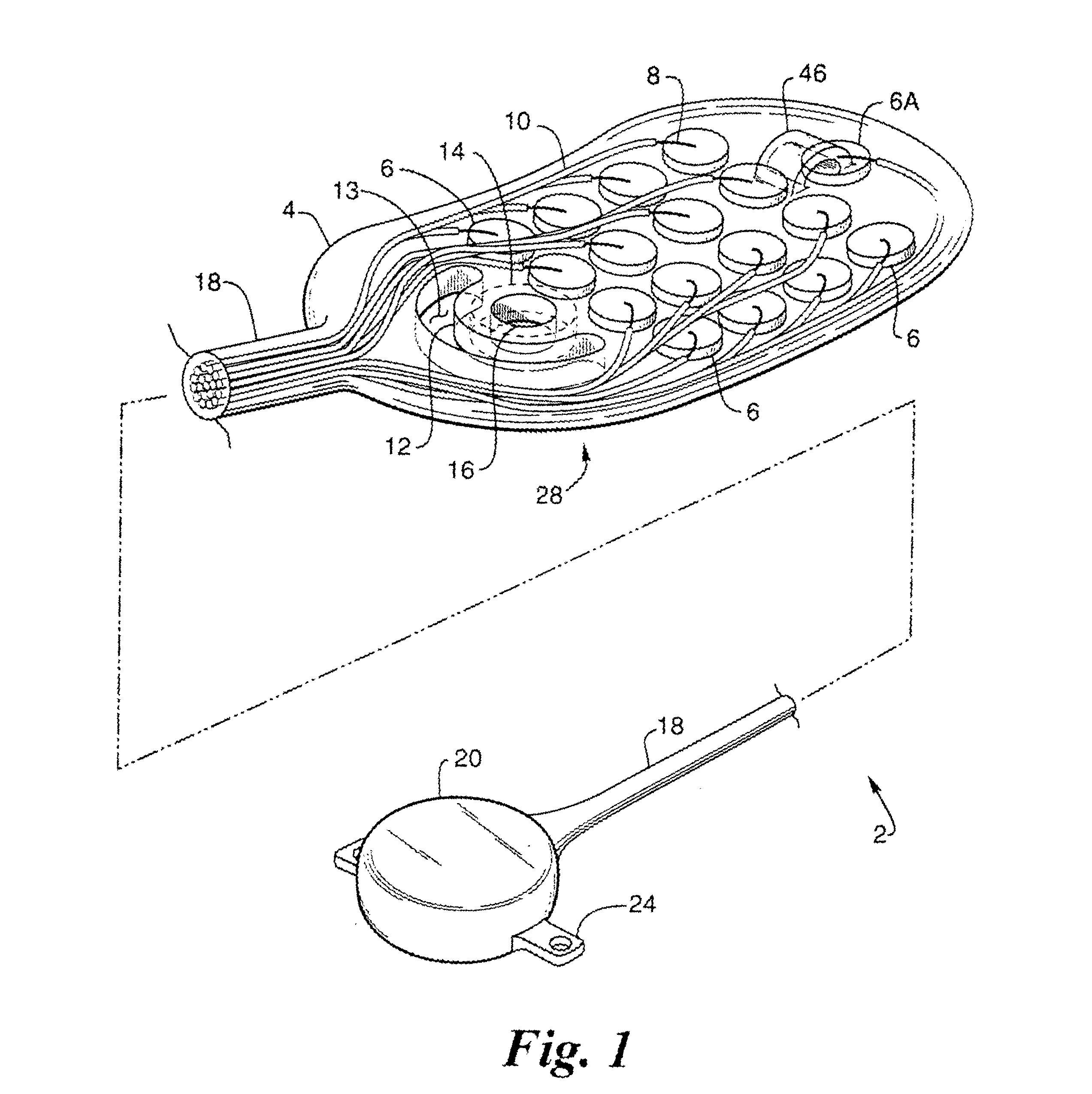
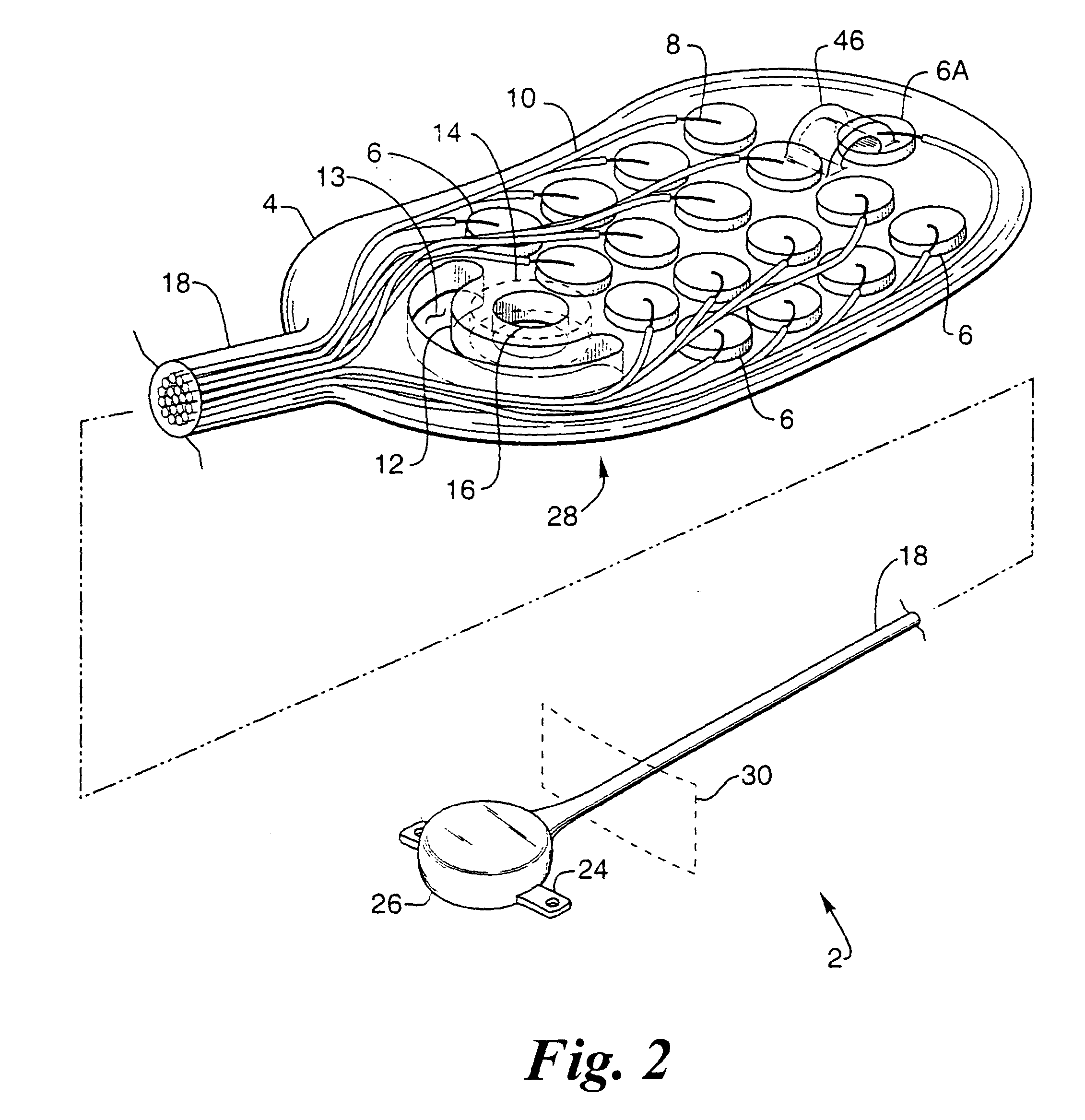
[0036]FIG. 1 provides a perspective view of a preferred embodiment of the retinal electrode array (implanted by the surgical too of the resent invention), generally designated 2, comprising oval-shaped electrode array body 4, a plurality of electrodes 6 made of a conductive material, such as platinum or one of its alloys, but that can be made of any conductive biocompatible material such as iridium, iridium oxide or titanium nitride, and single reference electrode 6A made of the same material as electrode 6, wherein the electrodes are individually attached to separate conductors 8 made of a conductive material, such as platinum or one of its alloys, but wh...
PUM
 Abstract
Description
Claims
Application Information