Hand-size structured-light three-dimensional metrology imaging system and method

a three-dimensional metrology and structured light technology, applied in the field of metalrology systems, can solve the problems of inability to fully automate automatic measurement routines, system lack of mobility and flexibility, and general lack of flexible semi-automated video tools of instruments, etc., and achieve the effect of improving imaging and/or measurement results

Active Publication Date: 2007-05-03
MITUTOYO CORP
View PDF9 Cites 80 Cited by
  • Summary
  • Abstract
  • Description
  • Claims
  • Application Information

AI Technical Summary

Benefits of technology

[0012] In accordance with another aspect of the invention, the device may include one or more alignment fixtures. The alignment fixtures may be interchangeably attached to or guide the metrology device to hold it at a desired focusing distance and / or orientation relative to a workpiece, for improving the imaging and / or measurement results. The alignment fixtures may also have a mechanism to help establish a correct and / or repeatable orientation of a workpiece and / or reference object relative to the metrology device.

Problems solved by technology

In general, such systems lack mobility and flexibility with regard to the fact that a large percentage of dimensional measurements are manually performed in workshops, office spaces, and at other sites that are too remote or inconvenient for access by a desktop-sized machine vision metrology system.
Furthermore, such instruments generally lack the flexible semi-automated video tools, and / or automatic measurement routine capabilities, that are used for measurement and analysis of images in larger machine vision systems.

Method used


Image

  • Hand-size structured-light three-dimensional metrology imaging system and method
  • Hand-size structured-light three-dimensional metrology imaging system and method
  • Hand-size structured-light three-dimensional metrology imaging system and method

Examples


Embodiment Construction

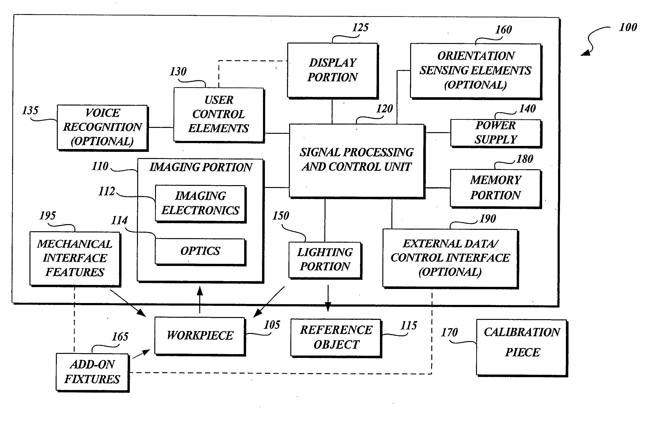
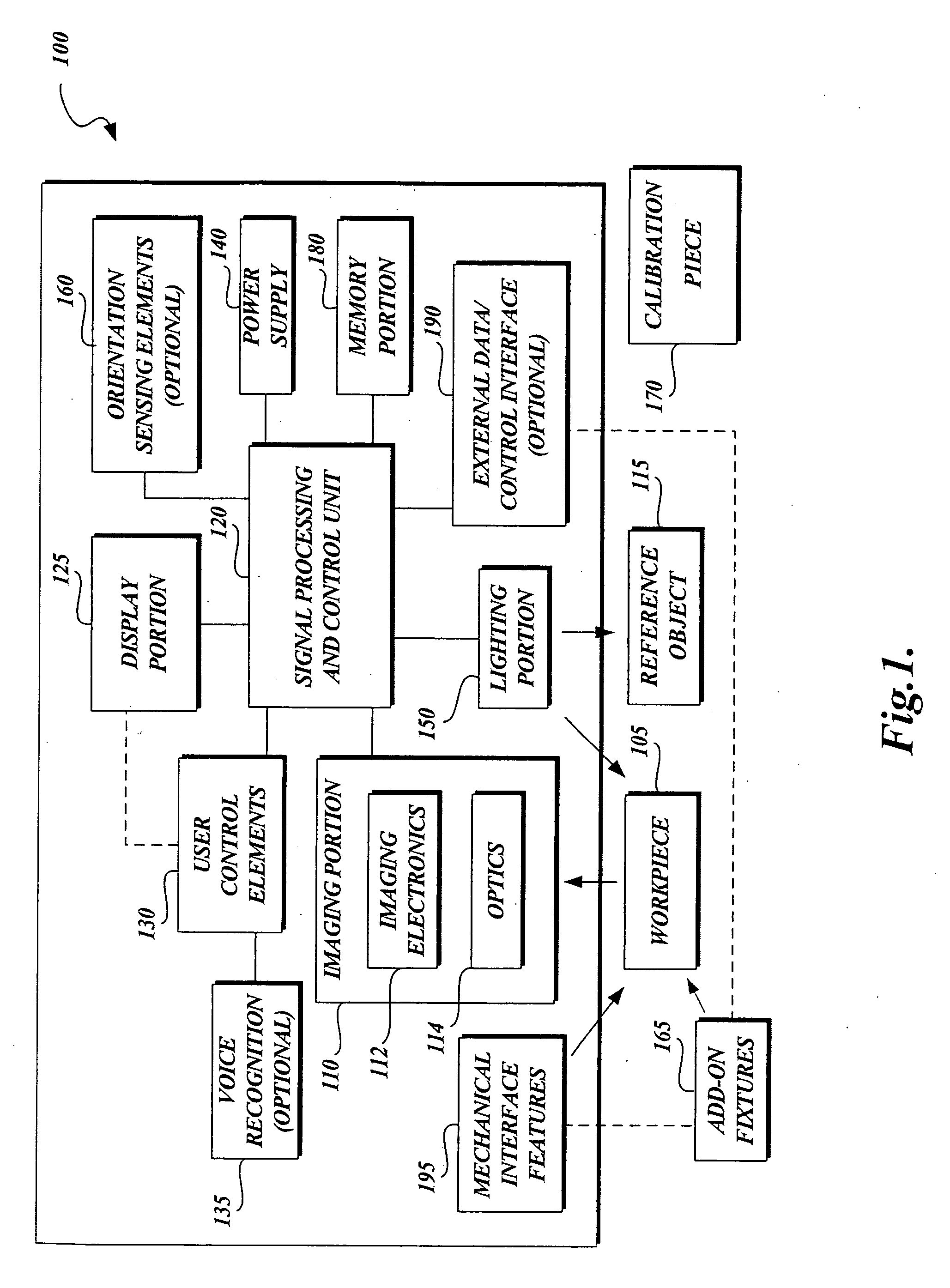
[0033]FIG. 1 is a block diagram of a hand-size structured-light three-dimensional metrology imaging system 100 (also referred to as the metrology system 100) in accordance with the present invention. The hand-size structured-light three-dimensional metrology imaging system 100 includes an imaging portion 110, a signal processing and control unit 120, a display portion 125, user control elements 130, a voice recognition portion 135, a power supply 140, a lighting portion 150, orientation sensing elements 160, add on fixtures 165, a memory portion 180, an external data / control interface 190, and mechanical interface features 195. The various portions of the hand-size structured-light three-dimensional metrology imaging system 100 may be interconnected by one or more power and signal bus connections, or by individual dedicated connections. Various signal interconnections may be made by wireless and / or optical means, if desired.

[0034] The hand-size structured-light three-dimensional me...


PUM


Abstract

A hand-size structured-light three-dimensional metrology imaging system and method. Laser illumination stripes are scanned across a workpiece surface for obtaining z-height and x-coordinate information. A Scheimpflug configuration is used. Utilizing this configuration, a laser illumination stripe across a raised workpiece portion will be shown in a contour image at the image sensor in a focused manner, such that the offsets along the contour image line due to the raised portions of the workpiece surface can be accurately converted to a z-height measurement. The y-axis positions associated with each of the contour images, used for reassembling the information from the contour images into a surface map for the workpiece, may be determined without the need for a position sensor, by including a reference object in the contour images.

Description

FIELD OF THE INVENTION [0001] The present invention relates to metrology systems, and more particularly, to a “hand-size” self-contained structured-light three-dimensional metrology imaging system and method. BACKGROUND OF THE INVENTION [0002] Measurement instruments using machine vision technology are widely used in quality assurance for both conventional and micro-sized parts and assemblies of machines, medical devices, and semiconductor products, etc. Most commercially available machine vision systems for dimensional measurement are desktop-sized or larger. In general, such systems lack mobility and flexibility with regard to the fact that a large percentage of dimensional measurements are manually performed in workshops, office spaces, and at other sites that are too remote or inconvenient for access by a desktop-sized machine vision metrology system. Smaller, “hand-size” type dimensional measurement instruments, whether using cameras, structured light triangulation, or contact ...

Claims


Application Information

Patent Timeline
Patent Type & Authority Applications(United States)
IPC IPC(8): G01B11/24
CPCG01B11/25G06T7/0057G06T7/521
Inventor TOBIASON, JOSEPH DANIELNAHUM, MICHAELGLADNICK, PAUL
Owner MITUTOYO CORP
Why Eureka
Try Eureka