Low-inductance electromagnetic drive without driving the magnetic flux circuit

a low-inductance electromagnetic and magnetic flux technology, applied in the field of electromagnetic drives, can solve the problems of short-circuit ring may not apply positive and equivalent feedback excitation, frequency response and distortion of the loudspeaker, and the power amplifier used for driving the loudspeaker to suffer from defective feedback, etc., and achieve the effect of reducing phase instability

Inactive Publication Date: 2007-05-03
YUYAO TEMPERATURE INSTR FACTORY CO LTD
View PDF5 Cites 7 Cited by
  • Summary
  • Abstract
  • Description
  • Claims
  • Application Information

AI Technical Summary

Benefits of technology

[0005] In view of the disadvantages of the above prior art, the object of the present invention is to provide a low-inductance electromagnetic drive without driving the magnetic flux circuit, in which the inductive impedance changes are small when the frequency changes, so that the electric energy, obtained by the electromagnetic energy converter, changes are small with the variation of inductive impedance, the phase instability is decreased, and the sound distortion led by the magnetic flux circuit excitation is basically eliminated.

Problems solved by technology

At the same time, because of the existence of inductance, the phase shifts will occur due to the voltage and the current through the loudspeaker, which will lead to defective feedback to the power amplifier used for driving the loudspeaker.
When the phase of voltage changes in combination with the effect of magnetic energy converting to electric energy, the energy stored in the magnetic circuit of loudspeaker will act on the drive coil via the differential resistance of the power amplifier, which will lead to frequency response and distortion of the loudspeaker, earphone and sonic transducer.
But because only part of the energy produced by drive coil can just be passively consumed by the short-circuit ring, and the short-circuit ring is not connected electrically with the drive coil, the short-circuit ring may not apply positive and equivalent feedback excitation to the magnetic circuit system to counteract the harmful excitation of the drive coil on the magnetic circuit system.

Method used


Image

  • Low-inductance electromagnetic drive without driving the magnetic flux circuit
  • Low-inductance electromagnetic drive without driving the magnetic flux circuit
  • Low-inductance electromagnetic drive without driving the magnetic flux circuit

Examples


first embodiment

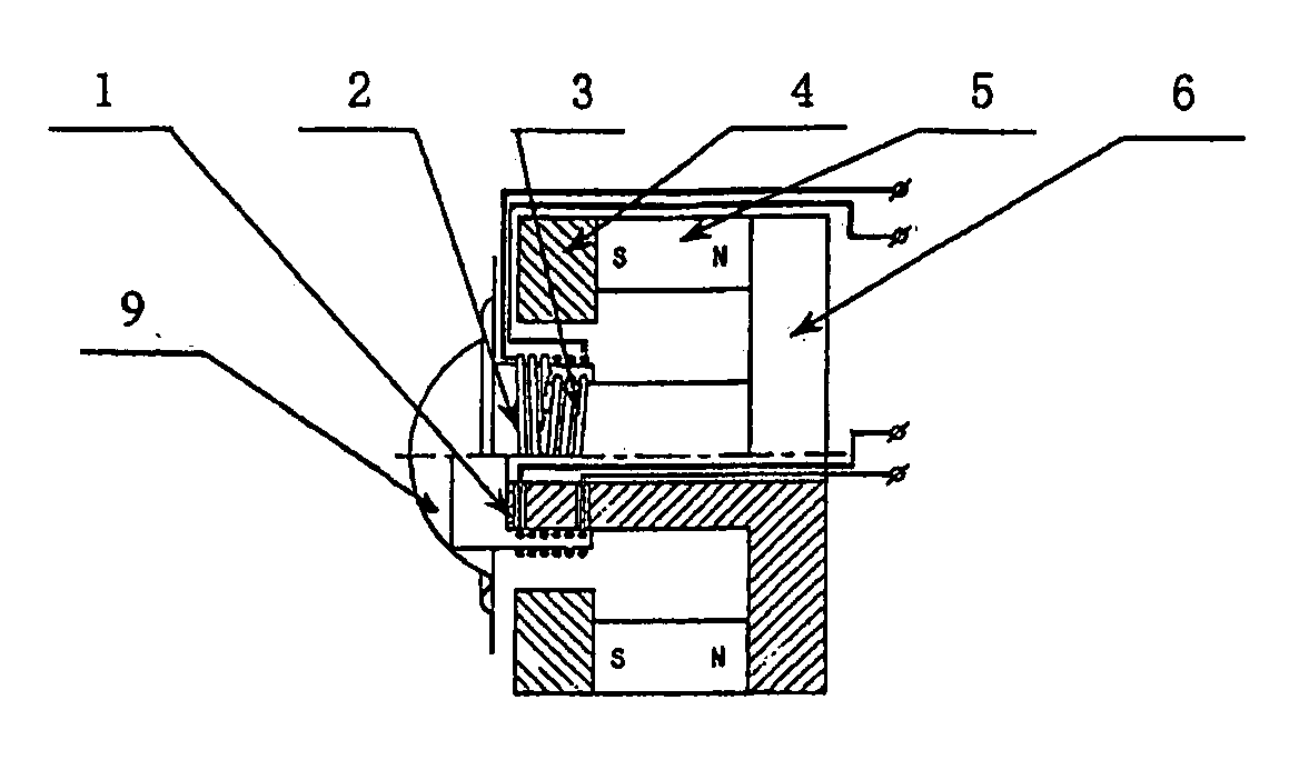
[0039] In the present invention as shown in FIG. 1, an electromagnetic drive comprises a magnetic pole 1, a drive coil 2, a first fastening coil 3, an upper magnetic-inductive board 4, a permanent magnet 5 and a lower magnetic-inductive board 6. The magnetic pole 1 is integrated with the lower magnetic board 6, and the permanent magnet 5 is connected with both the upper magnetic-inductive board 4 and the lower magnetic-inductive board 6. The drive coil 2 is arranged on the magnetic pole 1; the first fastening coil 3 is wrapped and fixed on the magnetic pole 1 adhesively; the drive coil 2 is connected with the first fastening coil 3 in opposite phase.

second embodiment

[0040] In the present invention as shown in FIG. 2, an electromagnetic drive comprises a magnetic pole 1, a drive coil 2, a first fastening coil 3, an upper magnetic-inductive board 4, a permanent magnet 5 and a lower magnetic-inductive board 6. The magnetic pole 1 is connected with the lower magnetic board 6 as a whole, and the permanent magnet 5 is connected with both the upper magnetic-inductive board 4 and the lower magnetic-inductive board 6. The drive coil 2 is coupled on the magnetic pole 1; the first fastening coil 3 is fastened on the upper magnetic-inductive board 4 by adhesive; the drive coil 2 is connected with the first fastening coil 3 in opposite phase.

third embodiment

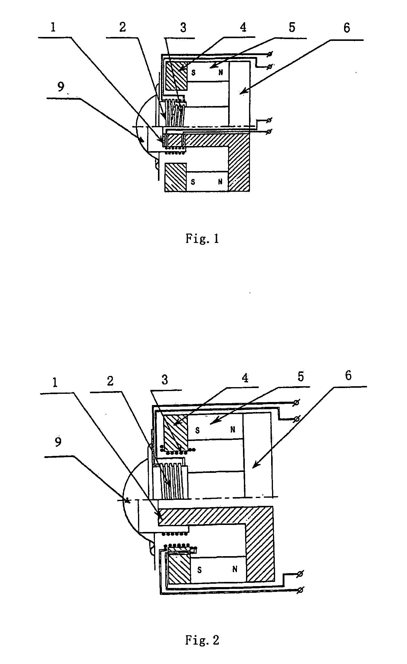
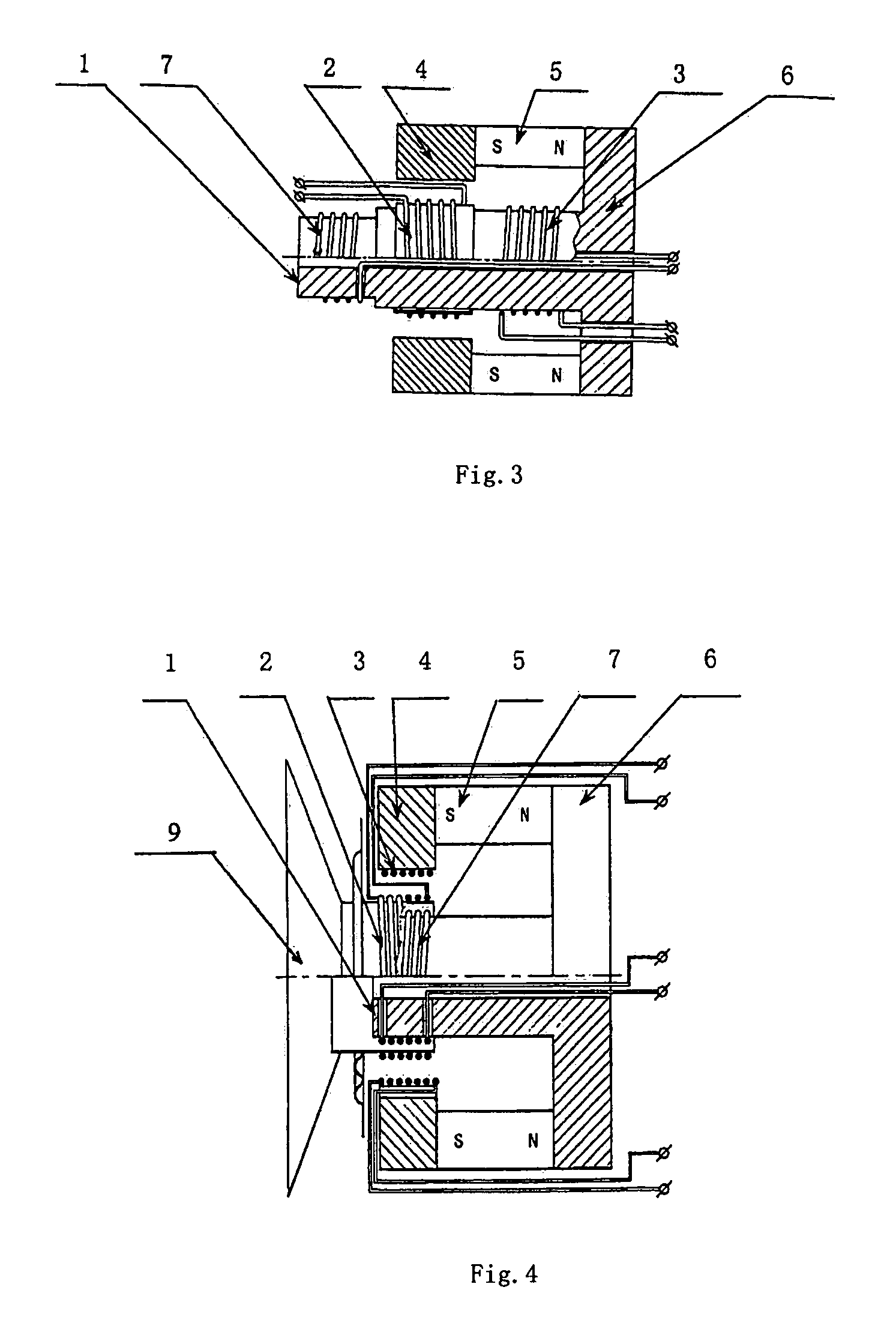
[0041] Referring to FIG. 3 of this invention, an electromagnetic drive comprises a magnetic pole 1, a drive coil 2, a first fastening coil 3, a second fastening coil 7, an upper magnetic-inductive board 4, a permanent magnet 5 and a lower magnetic-inductive board 6. The magnetic pole 1 is integrated with the lower magnetic board 6, and the permanent magnet 5 is set between the upper magnetic-inductive board 4 and the lower magnetic-inductive board 6 and connected with both of them. The drive coil 2, the first fastening coil 3 and the second fastening coil 7 are arranged on the magnetic pole. The two fastening coils are connected with the drive coil in such a way that the quantity of inductance is minimum, and the first fastening coil 3 and the second fastening coil 7 are wrapped and fastened around the magnetic pole 1.


PUM


Abstract

The present invention relates to a low-inductance electromagnetic drive without driving magnetic flux circuit, which comprises a magnetic pole, a drive coil, an upper magnetic inductive board, a permanent magnet and a lower magnetic-inductive board. The magnetic pole is integrated with the lower magnetic-inductive board, and the permanent magnet is located between the upper magnetic-inductive board 4 and lower magnetic-inductive board 6. The drive coil is wrapped around the magnetic pole and is movable in the axial direction. The electromagnetic drive further comprises the fastening coil, and the fastening coil is fastened to a certain proper place of the magnetic flux circuit of the drive coil. Furthermore, the fastening coil is connected with the drive coil in opposite phase. The present invention is characterized in that the drive source applies the excitation to the fastening coil in an equivalent quantity as the drive coil but in opposite phase, so that the excitation energy generated by the current flowing through the speaker for the magnetic flux circuit system is reduced to the minimum, the inductance quantity of the speaker is decreased to the minimum, and the sound distortion of the vibration system connected with the drive coil is decreased.

Description

CROSS-REFERENCE TO RELATED APPLICATIONS [0001] This application is a U.S. national stage application under 35 U.S.C. § 3.71 of international stage application number PCT / CN2004 / 000638, filed Jun. 14, 2004, which claims priority of Chinese patent application serial number 03149226.6, filed Jun. 18, 2003.TECHNICAL FIELD [0002] The present invention relates to an electromagnetic drive. More specifically, this invention relates to a low-inductance electromagnetic drive without driving magnetic flux circuit for improving the recording and playing quality of an audio signal. The electromagnetic drive of this invention can be used in loudspeakers, earphones and acoustic transducers. BACKGROUND OF THE INVENTION [0003] The audio and / or video apparatus is popular in people's lives. There are energy converters for converting sound energy to electric energy mutually in audio and / or video, such as loudspeakers, earphones and sonic transducers (microphones). The energy conversion between electric...

Claims


Application Information

Patent Timeline
Patent Type & Authority Applications(United States)
IPC IPC(8): H04R9/06H04R9/02
CPCH04R9/025H04R2209/021
Inventor WU, QUJUN
Owner YUYAO TEMPERATURE INSTR FACTORY CO LTD
Why Eureka
Try Eureka