
Electro-optical device for counting persons, or other, based on stereoscopic vision, and relative method

Inactive Publication Date: 2007-05-03
ETH LAB SRL
View PDF8 Cites 31 Cited by
  • Summary
  • Abstract
  • Description
  • Claims
  • Application Information

AI Technical Summary

Benefits of technology

[0025] According to another characteristic, in order to guarantee a correct functioning of the device even in the proximity of strong light sources, for example direct or reflected sunlight or powerful halogen lights, the image acquisition unit comprises one or more high-dynamic CMOS optical sensors with logarithmic response to incident light, which provide to convert the light radiation into an electric signal, preventing “blooming” effects.
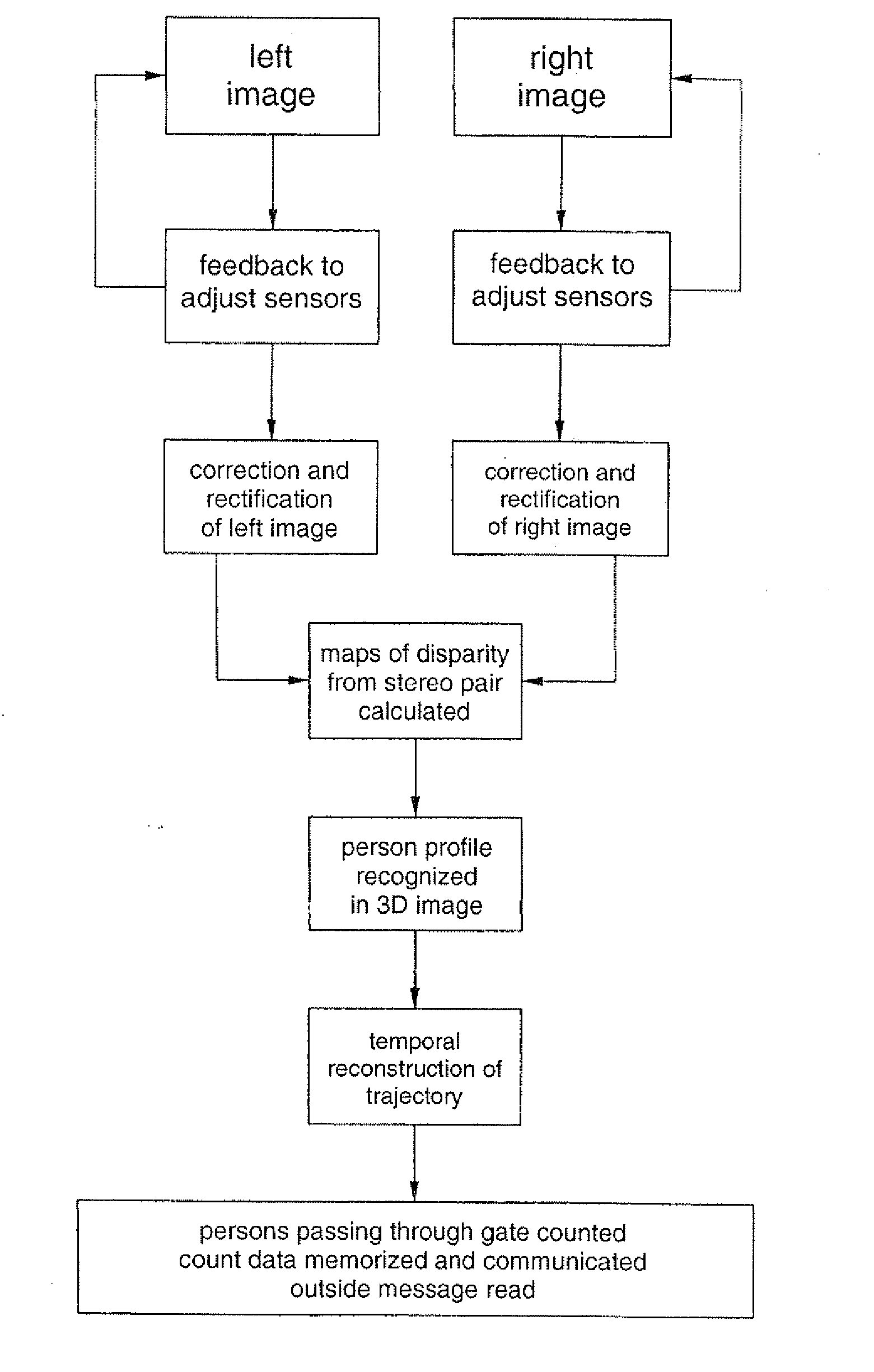
[0026] According to the present invention, the device comprises a neural network, implemented in software mode or in hardware mode, able to classify the three-dimensional profiles obtained from the processing of the stereoscopic images. The use of the neural network allows to learn, from examples, the three-dimensional profiles corresponding to persons filmed from a determinate perspective and to discriminate these profiles from those of objects or other structures. The ability to recognize and classify three-dimensional forms allows to reduce errors in counting due to the simultaneous presence of persons and extraneous objects in the control zone.
[0028] In an alternative form of embodiment, the different units that make up the system are integrated on a single silicon chip, that is, a System on Chip, by means of VLSI technology. This extreme integration technology allows to considerably reduce size, costs and consumption.
[0029] In order to further reduce costs and size, instead of two or more optical sensors equipped with lens, it is possible to acquire the stereoscopic images by means of an optical system configured to project different perspectives onto different portions of a single optical sensor of the CMOS type.
[0030] Even though so far the present invention has been described as a unit in itself, it is clear that various devices according to the invention can be interconnected through a line of digital communication so as to produce a network of sensors that cover several gates. In this way, the present invention can be employed to control the flow of persons through areas or buildings with different access gates.

Problems solved by technology

However, these devices have a considerable disadvantage: given the point nature of the detection, they do not allow to determine the shape of the object detected, and therefore to discriminate one object from another.
Consequently, the performance and reliability of such systems are compromised in situations of crowding, where two or more persons in close contact enter and / or leave through a gate, or by the presence of bulky objects such as suitcases, rucksacks, trolleys, umbrellas, etc.
Moreover, systems consisting of multiple point sensors have considerable problems of gauging and pointing that determine a high cost of installation and maintenance.
Systems based on the detection of movement alone suffer from errors caused by shadows or moving reflections, or by sudden changes in the light situation.
Moreover, such systems are not able to detect the presence of static objects.
Recognition systems based on a 2D analysis of the images alone are not yet able to discriminate a given object from the background in typical real situations.
This is because the variation in the possible two-dimensional forms resulting from different perspectives or positions of the object, particularly in the presence of several moving objects, makes it extremely complex to analyze the scene.
U.S. Pat. No. 5,581,625 discloses a vision system based on stereoscopic analysis which is not able, however, to follow the movement of possible objects in the zone of interest.
US-A1-2004 / 0017929 discloses a stereoscopic vision system which is limited, however, to the detection of situations with fraudulent access to persons through a gate, such as tailgating or piggybacking.
This system consists of various separate components of considerable size (one component to acquire images, an image acquisition card, an industrial PC, etc.) which must be connected to each other, which entails a considerable increase in bulk and complexity which greatly limits the applicability of the system in restricted spaces.
Moreover, this system requires a minimum illumination for correct functioning and employs CCD optical sensors which can be dazzled by strong illumination.

Method used


Image

  • Electro-optical device for counting persons, or other, based on stereoscopic vision, and relative method
  • Electro-optical device for counting persons, or other, based on stereoscopic vision, and relative method
  • Electro-optical device for counting persons, or other, based on stereoscopic vision, and relative method

Examples


Embodiment Construction

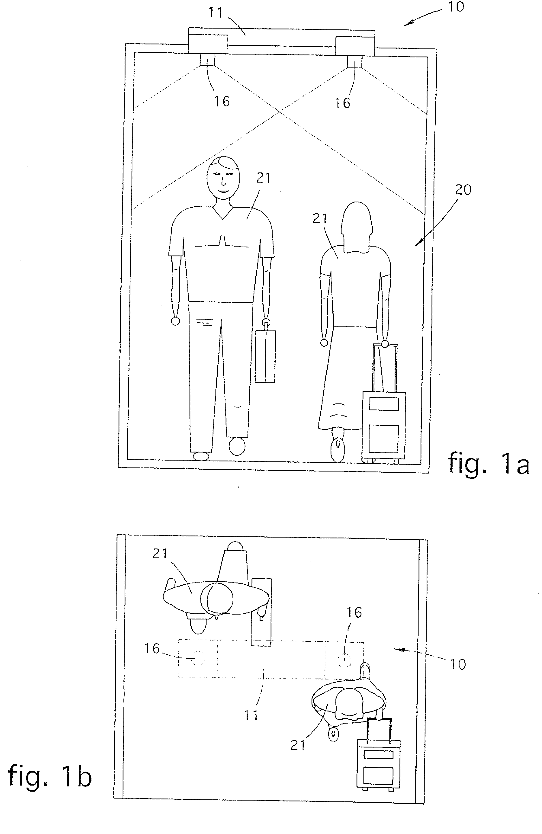
[0037] In FIG. 1, the device 10 is shown mounted above a gate, indicated in its entirety with the reference number 20, so that the entry and exit movement of a person 21 passing through it is ideally perpendicular to the line joining the two optics and that the viewing plane is parallel to the floor. Preferably, the distance of the device 10 from the floor must be at least 240 cm in order to guarantee the accuracy of the counting.

[0038] In the configuration step for counting persons, the neural network of the device 10 is trained to recognize the three-dimensional form of a person seen from above.

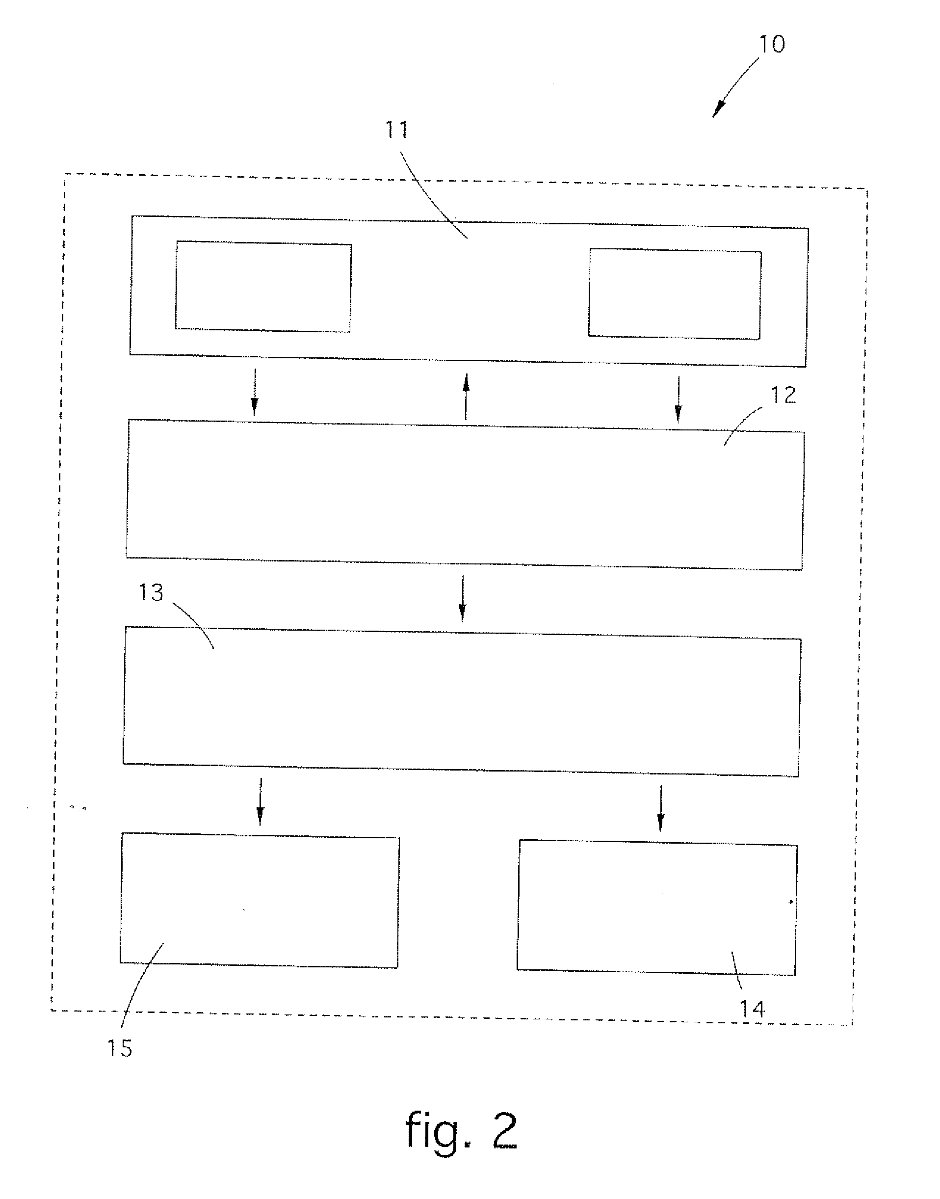
[0039] With reference to FIG. 2, the device 10 according to the present invention comprises, as essential parts, an image acquisition unit 11, a parallel calculation unit 12 dedicated to the rectification of the images and to the calculation of the distance maps, a processing / calculation unit 13 to recognize the three-dimensional forms based on neural networks and to calculate the traject...


PUM


Abstract

Electro-optical device for counting persons, or other, which comprises at least a unit for acquiring synchronized stereoscopic images and at least a processing unit which rectifies the stereoscopic images detected by the acquisition unit and counts the persons present in the field of vision of the acquisition unit.

Description

FIELD OF THE INVENTION [0001] The present invention concerns an integrated electro-optical device for counting persons who pass through a gate, or stay in a delimited zone. The counting device according to the invention is suitable to reconstruct the three-dimensional profile of an area subjected to visual control by means of stereoscopic vision techniques. The counting of persons, or other moving forms, for example animals or objects, is obtained by separating objects from the background, discriminating the three-dimensional shape of the persons from the profiles generated by objects or structures, and by reconstructing the trajectory of the movement of the persons inside the detection zone. The invention is preferably applied in the field of public transport (buses, trains, subway) or the control of areas or buildings open to the public where it is necessary to count the number of persons present. [0002] The invention also concerns the counting method carried out by the device. BA...

Claims


Application Information

Patent Timeline
IPC IPC(8): G06K9/62G06K9/00
CPCG06K9/00778G06T7/0075G06T7/593G06V20/53
Inventor CRESPI, BRUNOSARTORI, ALVISE
Owner ETH LAB SRL
Learn More