Tapered roller bearing and automotive pinion shaft supporting apparatus utilizing same tapered roller bearing

a technology automotive pinion shaft, which is applied in mechanical equipment, rotary machine parts, and bearings. it can solve the problems of reducing affecting the life of automotive pinion shaft supporting apparatus, and affecting the reliability of the bearing. reduce the effect of reduce the life and rigidity failure of automotive pinion shaft supporting apparatus, and reduce the running torque of tapered roller bearing

Active Publication Date: 2007-05-03
JTEKT CORP
View PDF4 Cites 13 Cited by
  • Summary
  • Abstract
  • Description
  • Claims
  • Application Information

AI Technical Summary

Benefits of technology

[0019] According to the automotive pinion shaft supporting apparatus, as is described above, since the contact area on the raceway surface and the rolling contact surfaces can be reduced suitably and the rolling viscous resistance between the inner and outer rings and the tapered rollers can be reduced, the rotation loss of the automotive pinion shaft supporting apparatus can be reduced. Furthermore, since the variability of the assembly torque when the tapered roller bearing is assembled can be suppressed, the reduction in life and rigidity failure of the automotive pinion shaft supporting apparatus can be suppressed, and gear noise can be reduced.
[0020] According to the tapere...

Problems solved by technology

However, there had been no attempt to grasp the crown as quantity so as to specify the crowning amount so imparted to thereby reduce the running torque of the tapered roller bearing.
However, it is often the case that this assembly torque varies.
In the even that the assembly torque varies, there may occur in a case where the preloading cannot be imparted accurately, leading to a risk that a preload that is imparted to the relevant bearing varies.
In the event that the preload that is imparted t...

Method used


Image

  • Tapered roller bearing and automotive pinion shaft supporting apparatus utilizing same tapered roller bearing
  • Tapered roller bearing and automotive pinion shaft supporting apparatus utilizing same tapered roller bearing
  • Tapered roller bearing and automotive pinion shaft supporting apparatus utilizing same tapered roller bearing

Examples


example

[0113] Next, the results of a comparison study will be described which was made using an example according to the invention and a comparison example in which specific numerical values were set, respectively. Main specification data of the example of the invention and the comparison example are shown in Table 1.

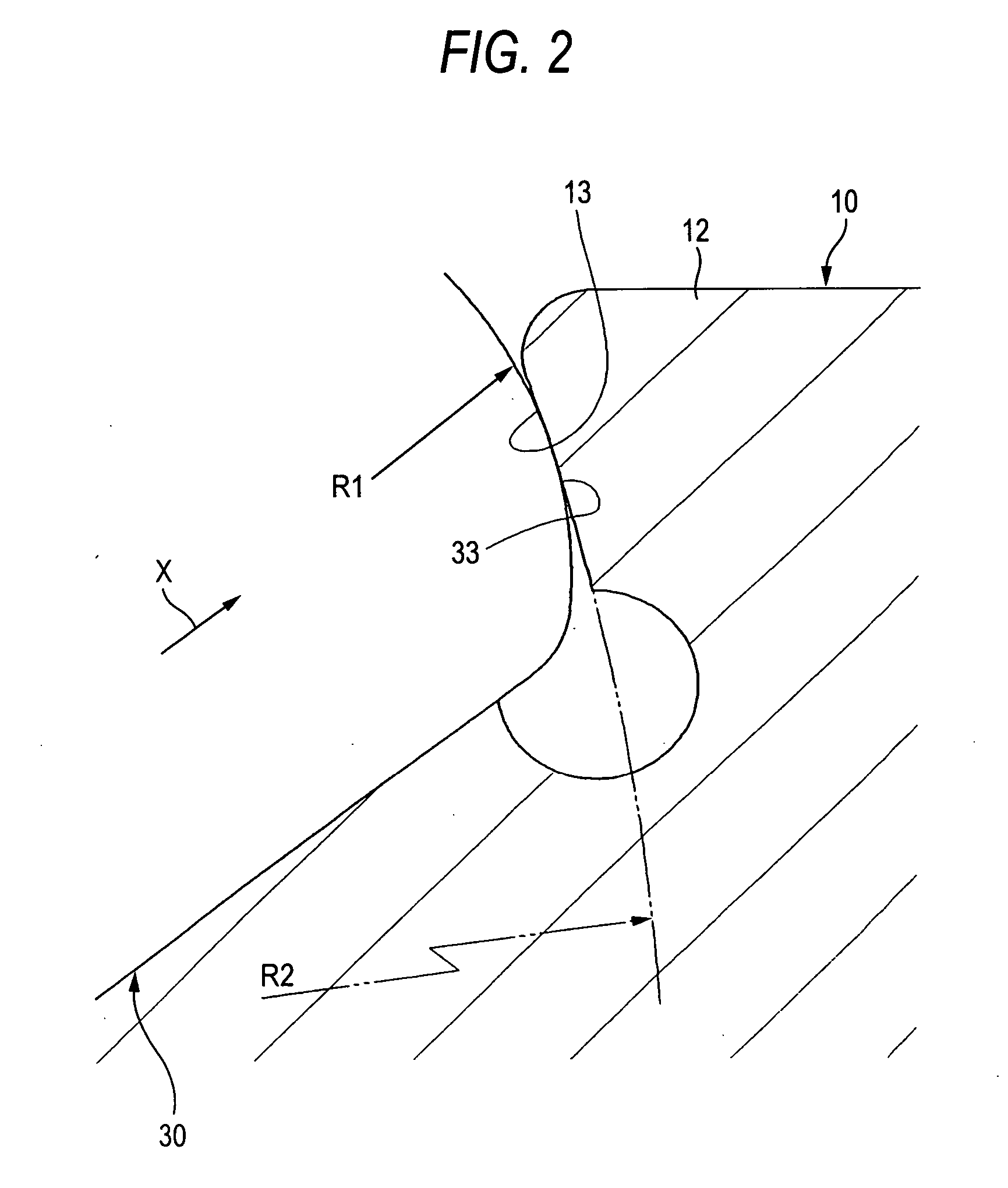
TABLE 1Exam-Compar-ple ofisonInven-Exam-Bearing SpecificationstionpleMainBore Diameter (mm)34.934.9DimensionsOutside Diameter (mm)72.272.2Width (mm)25.425.4CrowningOuter Ring Crowning Amount (μm)407Inner Ring Crowning Amount (μm)3512Roller Crowning Amount (μm)54Total Crowning Amount (μm)8527Outer Ring Crowning Rate (%)4726Roller Crowning Rate (%)1230Inner Ring Crowning Rate (%)4144Surface Roughness of Roller Large End Face0.040.02(σ1, μm)Surface Roughness of Inner Ring Large Rib Surface0.030.02(σ2, μm)Ratio between Curvature radius0.310.86of Roller Large End Face and Curvature radiusof Inner Ring Large rib surface (R1 / R2)

[0114] As to the crowning, the example of the inventio...


PUM


Abstract

A tapered roller bearing according to the invention is such that when an arithmetical mean roughness as a surface roughness of a large end face of a tapered roller is σ1 and an arithmetical mean roughness as a surface roughness of a large rib surface of an inner ring is σ2, σ1 is 0.04 μm or larger, and a composite roughness that is expressed by a square root of a sum of a squared value of σ1 and a squared value of σ2 is 0.17 μm or smaller. Raceway surfaces of an outer ring and the inner ring and a rolling contact surface of the tapered roller are crowned, and a total crowning amount is set to 50 μm or larger, an outer ring crowning rate is set to 40% or larger, and a roller crowning rate is set to 20% or smaller.

Description

BACKGROUND OF THE INVENTION [0001] The present invention relates to a tapered roller bearing which is preferably used in an automotive pinion shaft supporting apparatus as in a differential and a transaxle and in a transmission of a vehicle or the like, and an automotive pinion shaft supporting apparatus which uses the tapered roller bearing. [0002] In recent years, there has been increasing a demand for improvement in fuel economy of motor vehicles, and in association with the demand, there is expressed a desire to reduce the running torque of tapered roller bearings which are used to support rotational shafts of transmissions and differentials installed on those motor vehicles. [0003] In these situations, as a method of reducing the running torque of a tapered roller bearing, there is a method of reducing the rolling friction of a tapered roller bearing by crowning rolling contact surfaces of tapered rollers and raceway surfaces of inner and outer rings. [0004] As the method like ...

Claims


Application Information

Patent Timeline
IPC IPC(8): F16C33/58F16H57/021F16H57/037
CPCF16C33/36F16C2240/50F16C19/364F16C23/088F16C33/585F16C2361/61F16C19/225F16C2240/54F16C2240/70F16C33/366
Inventor MATSUYAMA, HIROKICHIBA, HIROYUKITODA, KAZUTOSHI
Owner JTEKT CORP
Why Eureka
Try Eureka