

Rotary cutting tool with non-uniform distribution of chip-breaking features
- Summary
- Abstract
- Description
- Claims
- Application Information
AI Technical Summary
Benefits of technology
Problems solved by technology
Method used
Image

Examples
Embodiment Construction
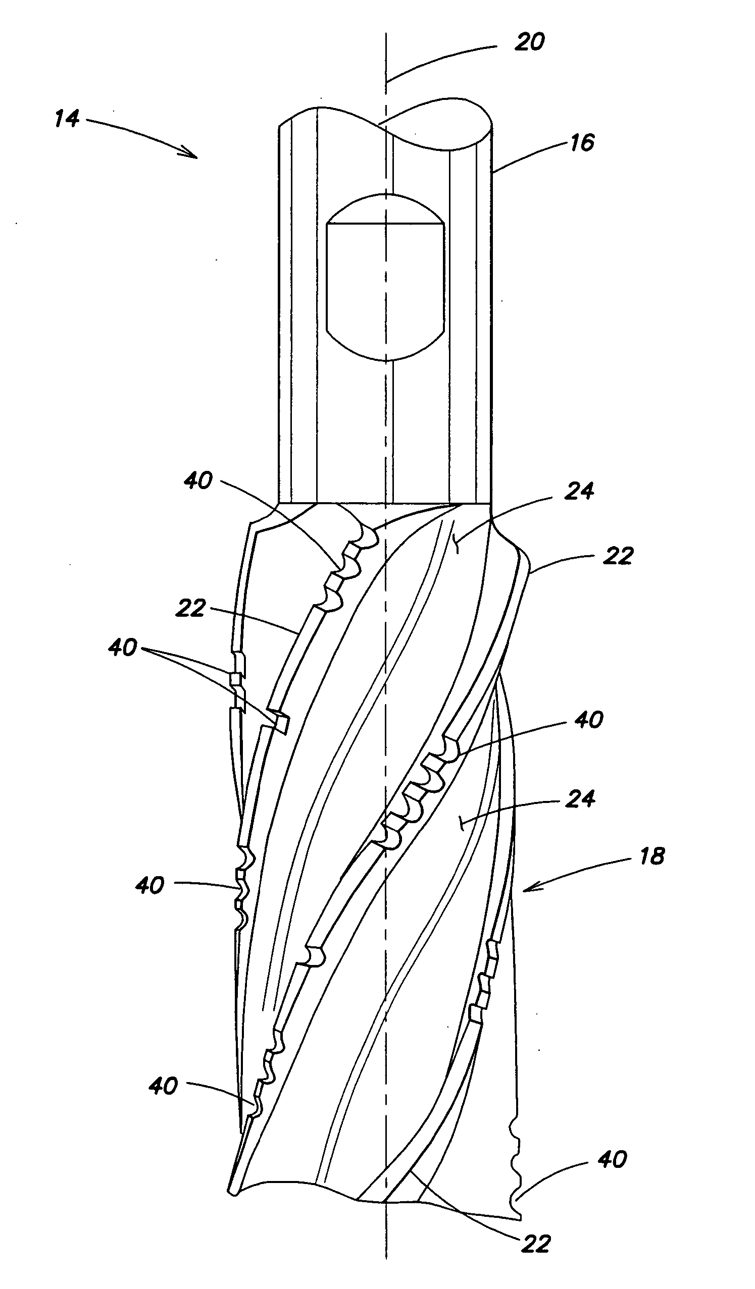
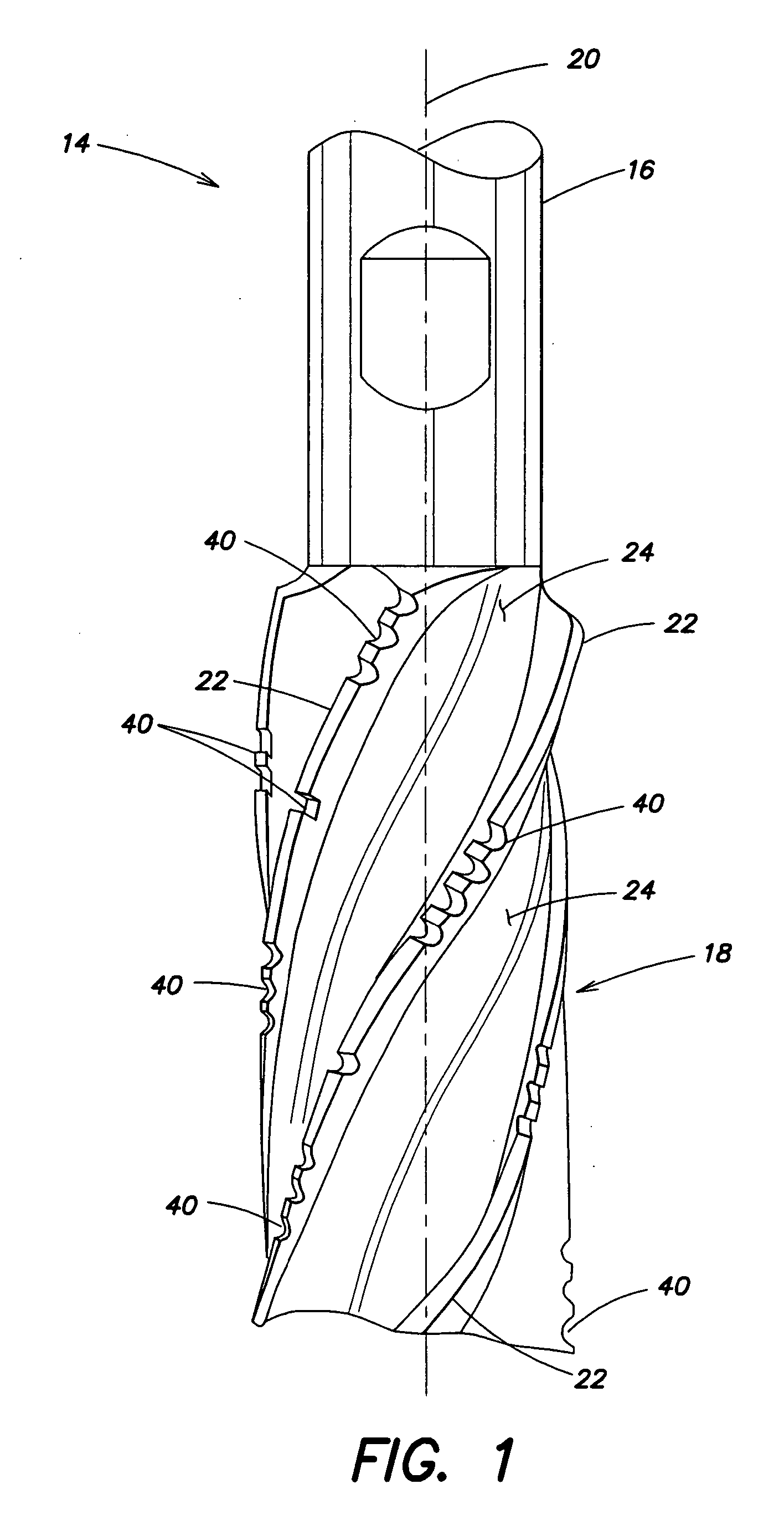
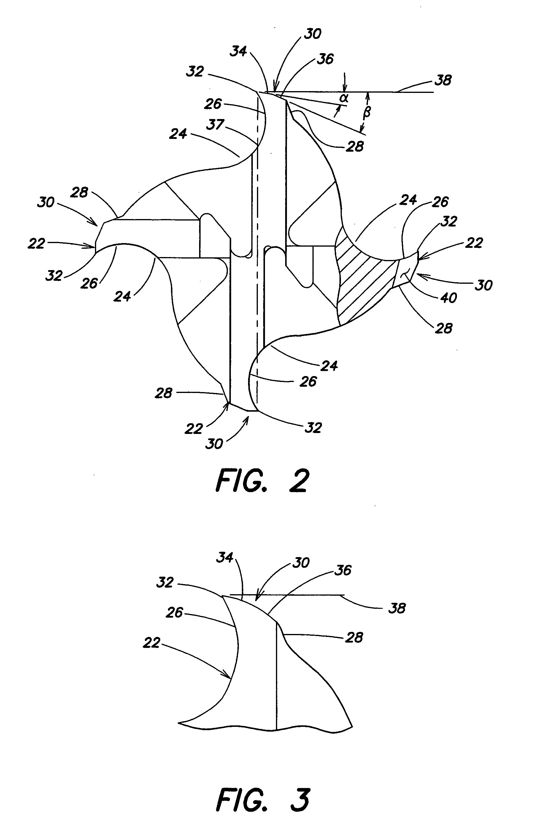
[0032] Now referring to FIGS. 1-3, a rotary cutting tool 14 is provided that includes a shank portion 16, a cutting portion 18, and a longitudinal axis 20. The overall shape of the cutting portion 18 may be, but is not limited to, a cylindrical shape or a frustoconical shape. The cutting portion 18 includes a plurality of blades 22 separated by flutes 24 extending the length of the cutting portion 18. Each of the blades 22 has a leading face side 26, a trailing face side 28, and a land surface 30 bridging the leading face side 26 and trailing face side 28. The intersection between the leading face side 26 and the land surface 30 forms a cutting edge 32 for the respective blade 22. In some embodiments, the blades 22 and flutes 24 of the cutting portion 18 extend helically within the cutting portion 18, and in other embodiments, the blades 22 and flutes 24 are “straight flutes” that extend parallel to the longitudinal axis 20.
[0033] In some embodiments the land surface 30 of a blade ...
PUM
| Property | Measurement | Unit |
|---|---|---|
| Length | aaaaa | aaaaa |
| Distance | aaaaa | aaaaa |
Abstract
Description
Claims
Application Information