Instrument for electrosurgical excision procedure for the uterine cervix

a uterine cervix and electrosurgical technology, applied in the field of instruments for surgical excision of tissues, can solve the problems of cell burst microscopically, sample of tissue obtained may vary in amount and definition, leep is particularly prone to producing fragmented and burnt biopsy samples, etc., to facilitate the rotation of the instrument

Inactive Publication Date: 2007-05-03
APPLE MEDICAL CORP
View PDF20 Cites 24 Cited by
  • Summary
  • Abstract
  • Description
  • Claims
  • Application Information

AI Technical Summary

Benefits of technology

[0014] This invention relates generally to endocervical excision instruments which are specifically used for the excision of a tissue specimen from the transformation zone of a uterine cervix. Those instruments comprise various new embodiments of the Fischer device described above. In particular, the various configurations of the stop on the instrument facilitate rotation of the instrument in either direction without engaging or catching irregularities of the uterine cervix which could otherwise interfere with the smooth rotation of the instrument about its axis.

Problems solved by technology

Consequently, the cells heat rapidly, generating steam that causes the cells to burst microscopically.
One problem with LEEP is that the sample of tissue obtained may vary in amount and definition.
LEEP is particularly prone to producing fragmented and burnt biopsy samples if it is necessary to make multiple passes of the loop.
These problems with the samples reduce the accuracy of diagnosis.
Another problem with LEEP is incomplete removal of the lesion when excising the transformation zone.
This result can only worsen the patient's long-term prognosis and requires further procedures to remove the remaining abnormal cells.
The converse risk is removal of too much tissue which may result in cervical stenosis or incompetent cervix and / or sterility.
The primary cause of these problems is the inherent lack of stability of the loop, because it is generally on the distal end of a long handle for which there is no guiding support.
This lack of stability is exacerbated because the electrode itself can move in relation to the handle under the influence of drag as the electrode passes through the cervical tissue.
This compounds the difficulty of knowing exactly where the electrode is positioned at all times and adds to the difficulty of producing an accurate cut.
On occasion, the protruding end of the stop arm of the Fischer device, particularly a curved stop arm, has a tendency to engage or catch irregularities of the uterine cervix, thus interfering with the smooth rotation of the Fischer device about its axis.

Method used


Image

  • Instrument for electrosurgical excision procedure for the uterine cervix
  • Instrument for electrosurgical excision procedure for the uterine cervix
  • Instrument for electrosurgical excision procedure for the uterine cervix

Examples


Embodiment Construction

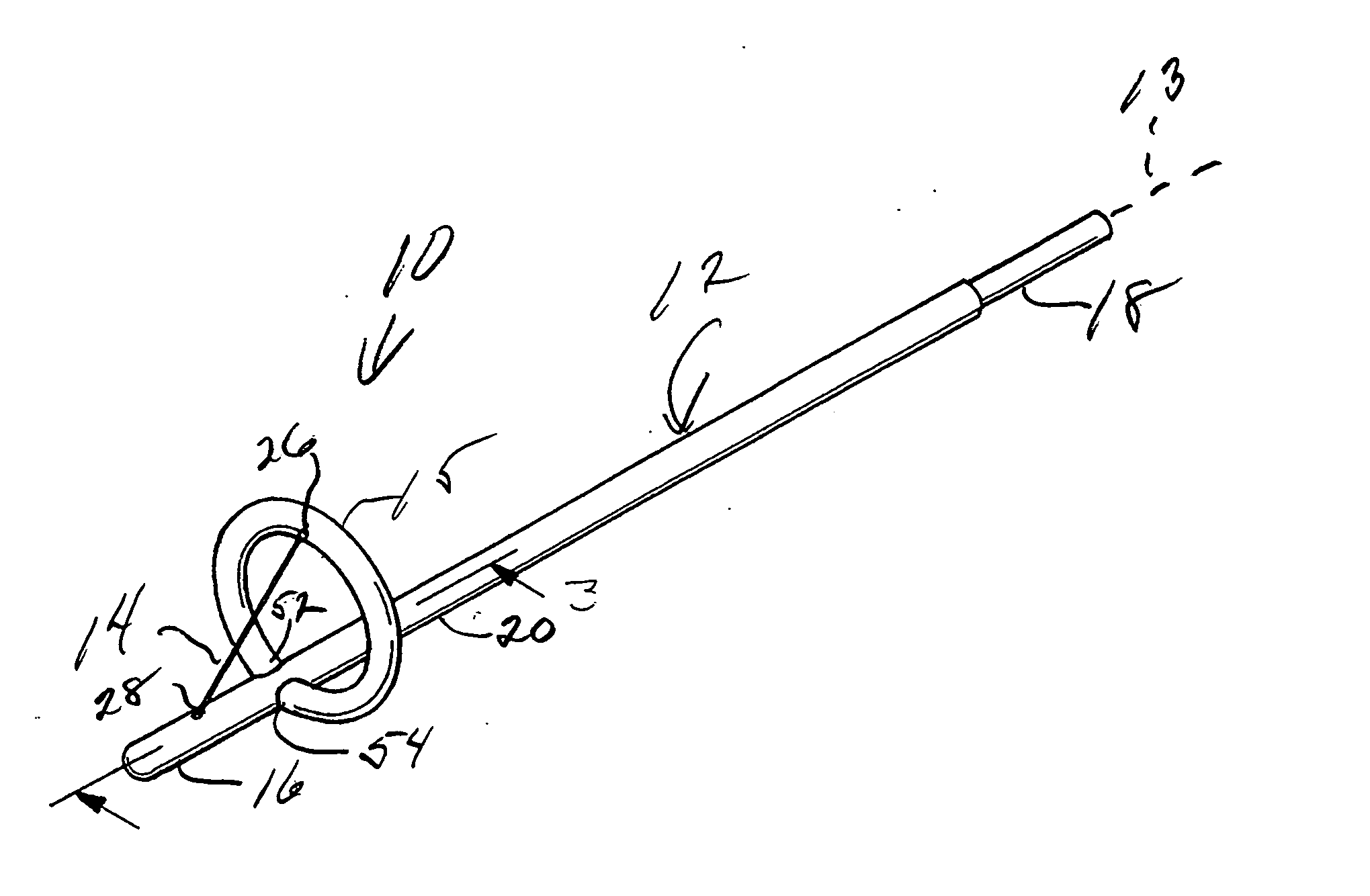
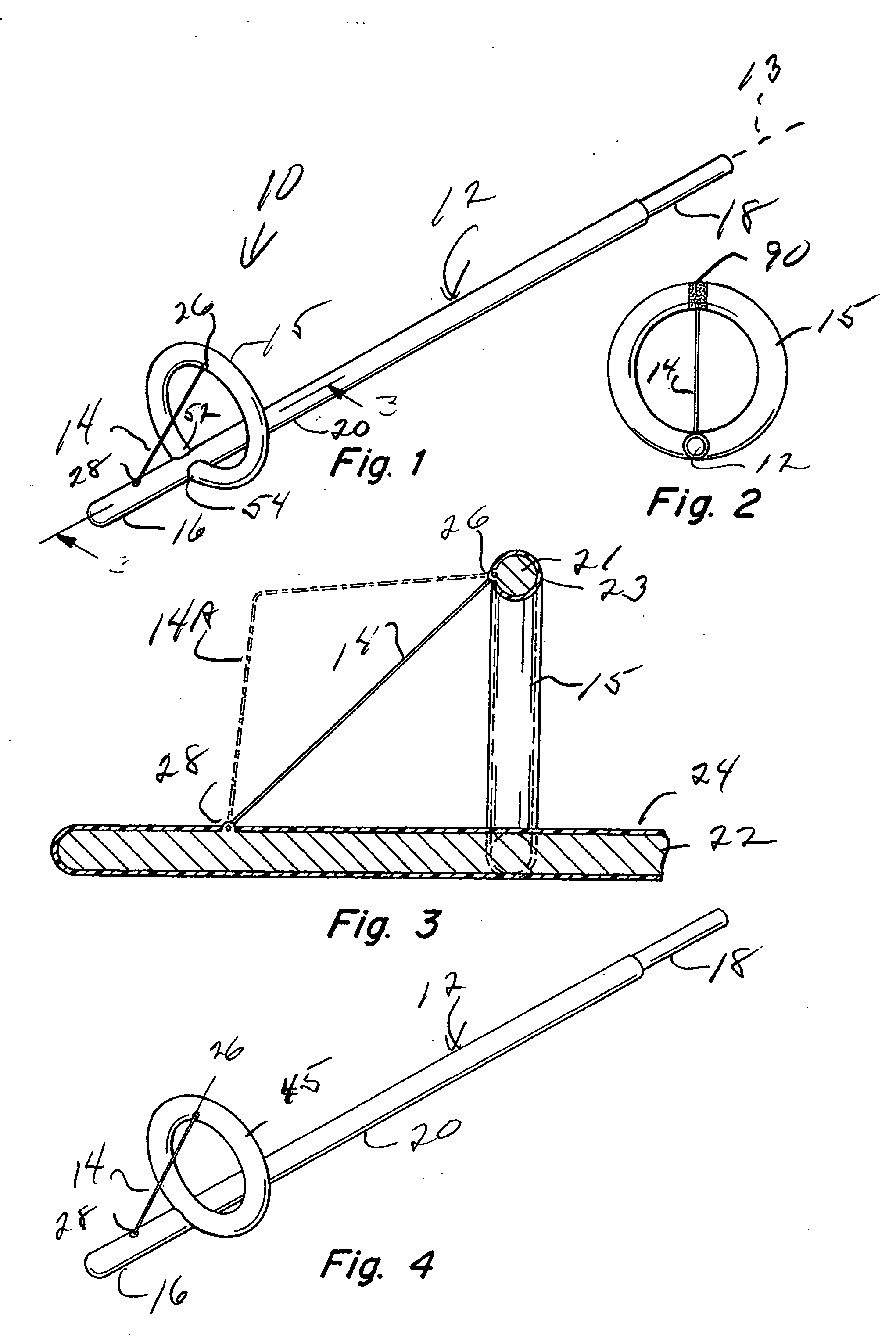
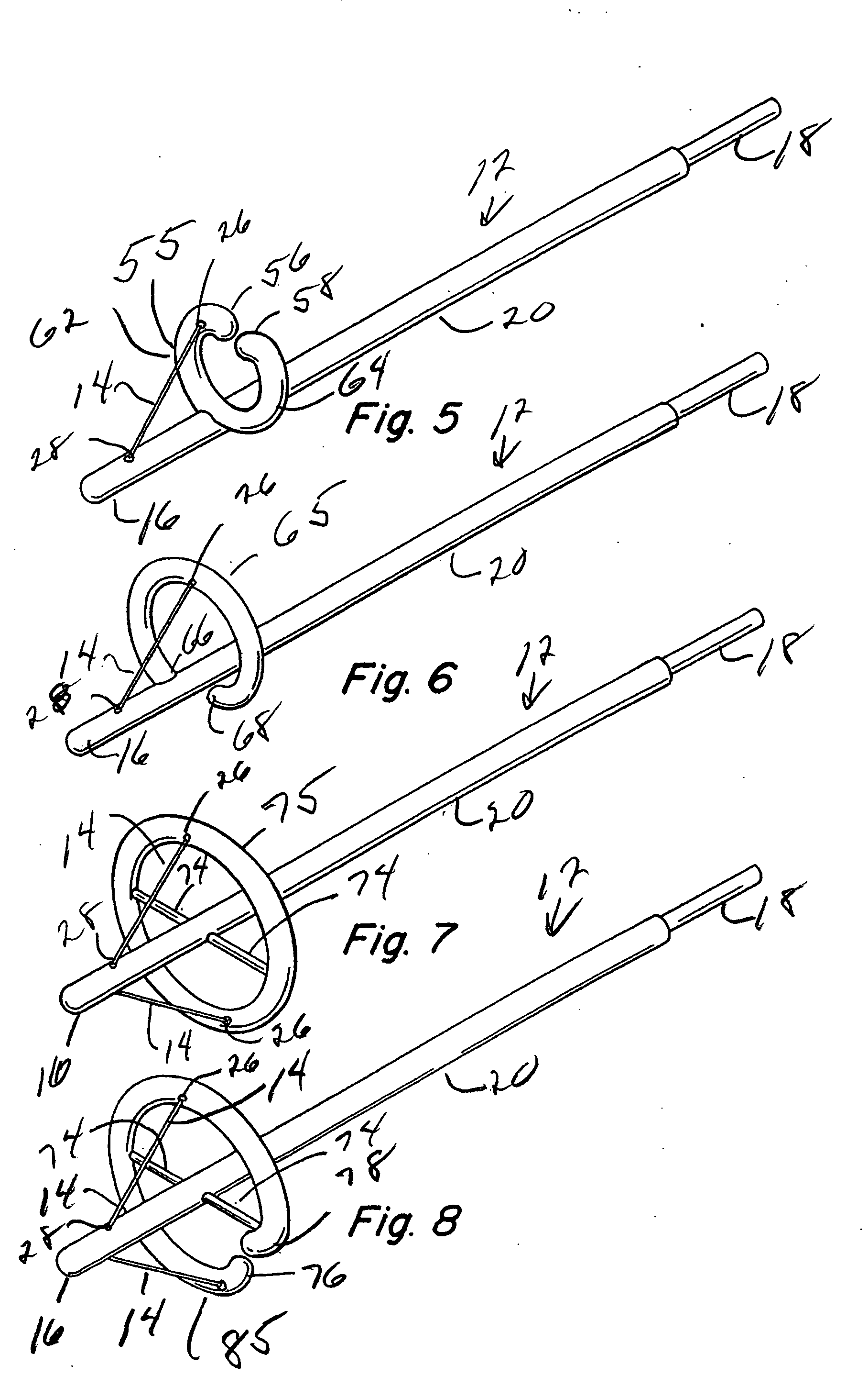
[0038] The present invention relates to instruments which are modifications of the Fischer cone biopsy device, as described in U.S. Pat. Nos. 5,554,159 and 5,403,310, which are incorporated herein by reference in their entirety. In one aspect of the invention, the stop is configured to have no protruding edges or ends. The stop is configured such that the central shaft or body member may be rotated about its axis in either a clockwise or a counterclockwise direction without any protruding edges or ends on the stop that may catch on irregularities in the uterine cervix. In one embodiment of this aspect, the stop has a substantially curved shape throughout its length. Typically, in this embodiment, the stop has a substantially circular configuration. This stop may extend over a complete 360° arc, or it may extend over any arc greater than 180°. In one embodiment, a substantially circular stop is mounted to the central shaft along one edge such that the shaft forms a tangent with respe...


PUM


Abstract

A cervical biopsy instrument that includes a central shaft defining a longitudinal axis and a stop extending laterally from the shaft. The stop typically is formed in substantially the shape of a circle in a plane disposed at substantially right angles to the central axis of the shaft. The instrument also includes an electrode extending from an endocervical portion of the shaft to the stop. The stop may be formed in the shape of a complete circle, or a partial circle. Any free ends are configured to be rounded and extend inwardly toward the shaft or away from the endocervical portion to prevent the presentation of sharp edges or the like which could be caught on irregularities of the uterine cervix. The stop may be affixed to the central shaft along a tangent, or ends of the stop may be affixed to the central shaft. In another embodiment, the stop encircles or partially encircles the shaft, with the shaft extending substantially through the center of the circle. In this embodiment, either one or two electrodes may be provided. Spokes support the stop with respect to the shaft. The spokes may be formed at an acute angle with respect to the shaft to extend away from the shaft toward the endocervical end thereof. These configurations allow the instrument to be rotated in either a clockwise or a counter-clockwise direction about the central axis of the shaft without fear of catching on the uterine cervix. In another aspect of the invention, a marker is provided on the stop to indicate the location of the electrode.

Description

BACKGROUND OF INVENTION [0001] 1. Field of Invention This invention relates generally to an instrument for the surgical excision of tissues, more particularly to an instrument for electrosurgically excising a tissue specimen from the transformation zone of the uterine cervix. [0002] 2. Background of the Invention [0003] Cancer of the uterine cervix, or cervical cancer, usually progresses slowly over an extended period from the first appearance of precancerous abnormalities. This gradual progression presents an opportunity for many patients to entirely avoid cervical cancer if they can benefit from preventive intervention. Even for those who do not, there is a good prognosis if the cancer is detected and treated early enough. [0004] Before malignant cells are found, the tissues of the cervix go through changes in which abnormal cells begin to appear, initially on the epithelial tissue on the surface of the cervix. This precancerous condition is known as dysplasia or cervical intraepi...

Claims


Application Information

Patent Timeline
Patent Type & Authority Applications(United States)
IPC IPC(8): A61B18/14
CPCA61B18/149A61B2018/00559A61B2018/144A61B2017/4225A61B10/0291
Inventor FISCHER, NATHAN R.
Owner APPLE MEDICAL CORP
Why Eureka
Try Eureka