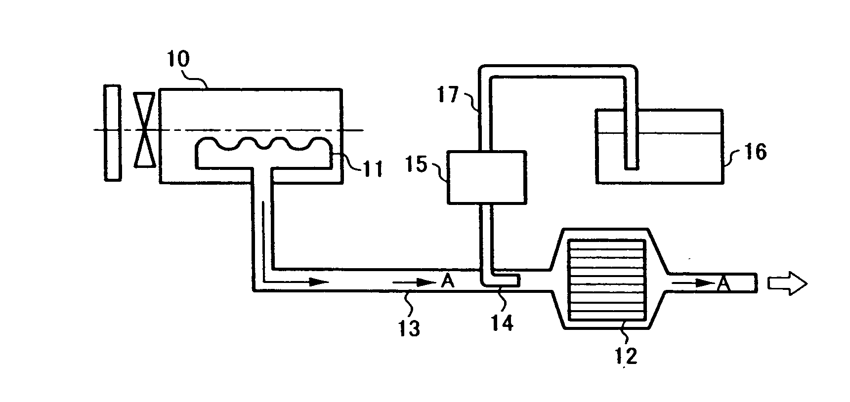
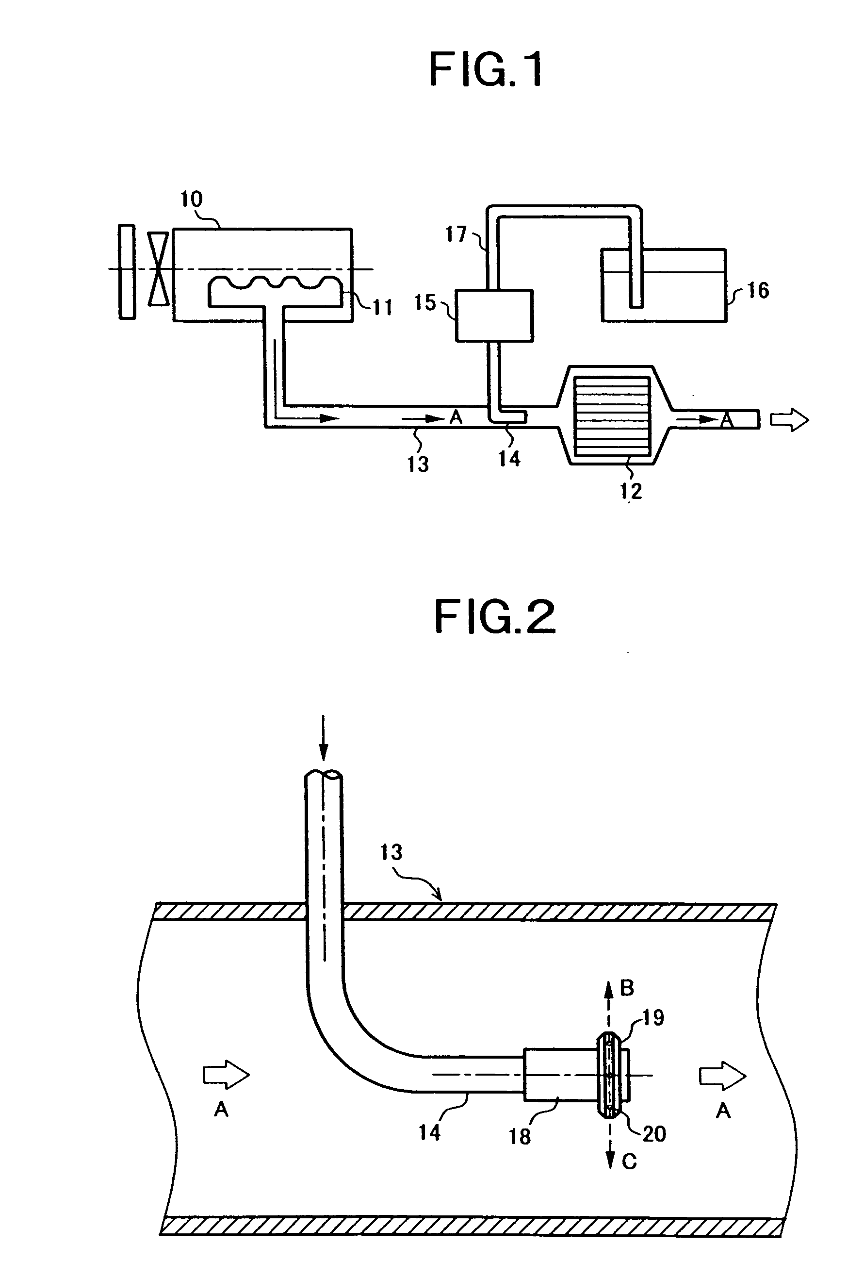
[0009] Therefore, the present invention addresses such problems, with an object of providing an engine exhaust gas purification apparatus in which clogging in an injection nozzle, which supplies a reducing agent to an exhaust gas flow on an upstream side of a reduction catalyst is prevented, and the mixing proportion of the reducing agent and the exhaust gas is improved, and the efficiency of NOx purification processing is improved.
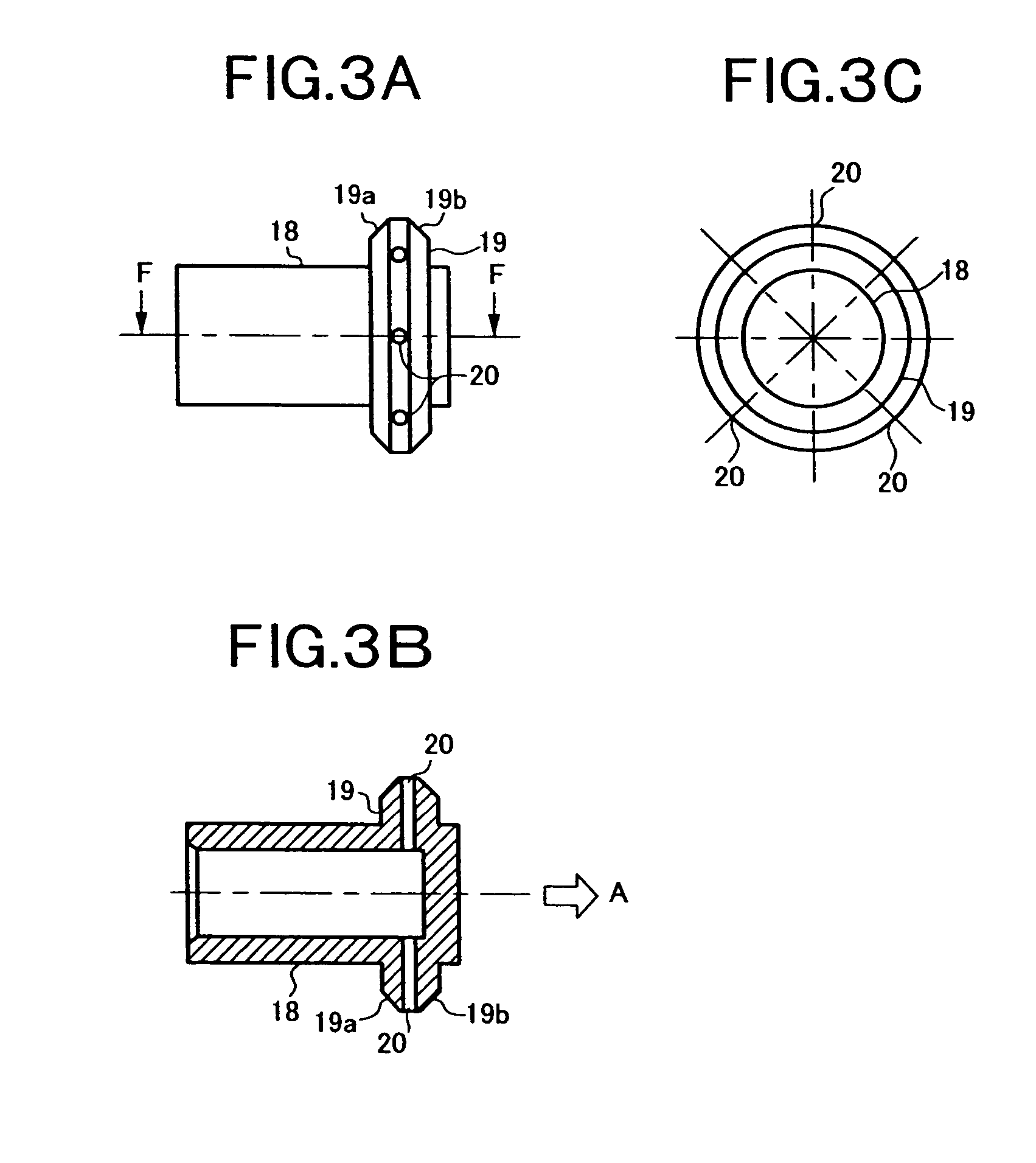
[0012] In accordance with the invention according to claim 2, there is provided a plurality of the injection holes, which are drilled in a radial pattern in an outward direction from the axial center of the tip end portion of the injection nozzle. As a result, the injection holes substantially evenly eject the reducing agent into all regions inside the exhaust gas passage of the exhaust
system.
[0015] According to the configuration of the invention according to claim 1, a reducing agent can be ejected in an outward direction from the axial center of an injection nozzle, from injection holes provided in a ring shaped protruding
ridge portion provided on the outer
peripheral surface of the exhaust gas downstream side end portion of the tip end portion of the injection nozzle, and the reducing agent can be ejected on the exhaust gas upstream side of the reduction catalyst. In this case, since the injection holes are formed in the ring shaped protruding ridge portion provided on the outer peripheral surface of the tip end portion of the injection nozzle, and do not directly open on a wide outer peripheral surface of the injection nozzle, then when injection stops the reducing agent does not become attached to or does not remain in the narrow region around the injection holes, or even if it becomes attached, the amount is small corresponding to the narrow region. Consequently, the reducing agent does not enter into the injection holes of the injection nozzle, so that clogging can be prevented. Therefore, the efficiency of NOx purification processing can be improved.
[0016] Furthermore, according to the configuration of the invention according to claim2, the reducing agent can be substantially evenly ejected into all regions inside the exhaust gas passage of the exhaust
system, from the plurality of injection holes drilled in the tip end portion of the injection nozzle in a radial pattern directed outward from the axial center. Consequently, a mixing proportion of the reducing agent and the exhaust gas can be improved. Therefore, the efficiency of NOx purification processing can be improved.
[0017] Furthermore, according to the configuration of the invention according to claim 3, the reducing agent can be ejected in a
diagonal direction on the downstream side, from the injection holes drilled inclined in a
diagonal direction towards the downstream side with respect to the exhaust gas flow direction. At this time, the reducing agent ejected in a
diagonal direction flows along the exhaust gas flow, preventing the reducing agent from becoming attached to the internal surface of the exhaust gas passage, and even in the case where the amount of exhaust gas is small, the reducing agent and exhaust gas are brought in good contact, and the mixing proportion thereof can be improved. Therefore, the efficiency of NOx purification processing can be improved.
[0018] Moreover, according to the configuration of the invention according to claim 4, due to the ring shaped protruding ridge formed in a shape that is tapered towards the outer peripheral surface, the flat surface portion in the vicinity of the injection holes are narrowed, and the reducing agent does not become attached to or does not remain in the narrowed region around the injection holes when injection from the injection nozzle stops, or the remaining amount thereof becomes small. Accordingly, clogging in the injection holes of the injection nozzle can be better prevented. Therefore, the efficiency of NOx purification processing can be improved.

