Manual bulk liquid pump control and distribution system

a distribution system and bulk liquid technology, applied in the direction of piston pumps, positive displacement liquid engines, packaging goods types, etc., can solve the problems of daily spills on each and every delivery, no longer any tolerance for these types of frequent spills, and high cost of underground storage of tanks, so as to reduce the stress of operation and ensure safety.

Active Publication Date: 2007-05-10
SAFETY PUMPING SYST
View PDF13 Cites 6 Cited by
  • Summary
  • Abstract
  • Description
  • Claims
  • Application Information

AI Technical Summary

Benefits of technology

[0018] The manual bulk liquid pump control and distribution system, primarily designed for the petroleum transportation industry, was built by the present inventor with safety and the environment at the forefront. The single flow reversing two-way valve handle controls the flow rate and volume of product and eases the stress of operation of this type of equipment. This design makes the unloading and loading of hazardous liquids as safe and efficient as possible along with the ability of removing all the liquid from the lines and hoses. The unique design meets the demands and the stringent requirements set by the Environmental Protection Agency, Air Resources Board, Department of Transportation, A.S.M.E, and various insurance companies.

Problems solved by technology

Accordingly, it is extremely expensive to put a tank underground.
There is no longer any tolerance for these types of frequent spills.
The fuel oil transportation industry and chemical transportation industry have problems that are similar to the petroleum industry.
This results in daily spills on each and every delivery, which is no longer an accepted practice.

Method used


Image

  • Manual bulk liquid pump control and distribution system
  • Manual bulk liquid pump control and distribution system
  • Manual bulk liquid pump control and distribution system

Examples


Embodiment Construction

[0086] Referring more specifically to the drawings, for illustrative purposes the present invention is embodied in the apparatus generally shown in FIG. 1 through FIG. 12. It will be appreciated that the apparatus may vary as to configuration and as to details of the parts, and that the method may vary as to the specific steps and sequence, without departing from the basic concepts as disclosed herein.

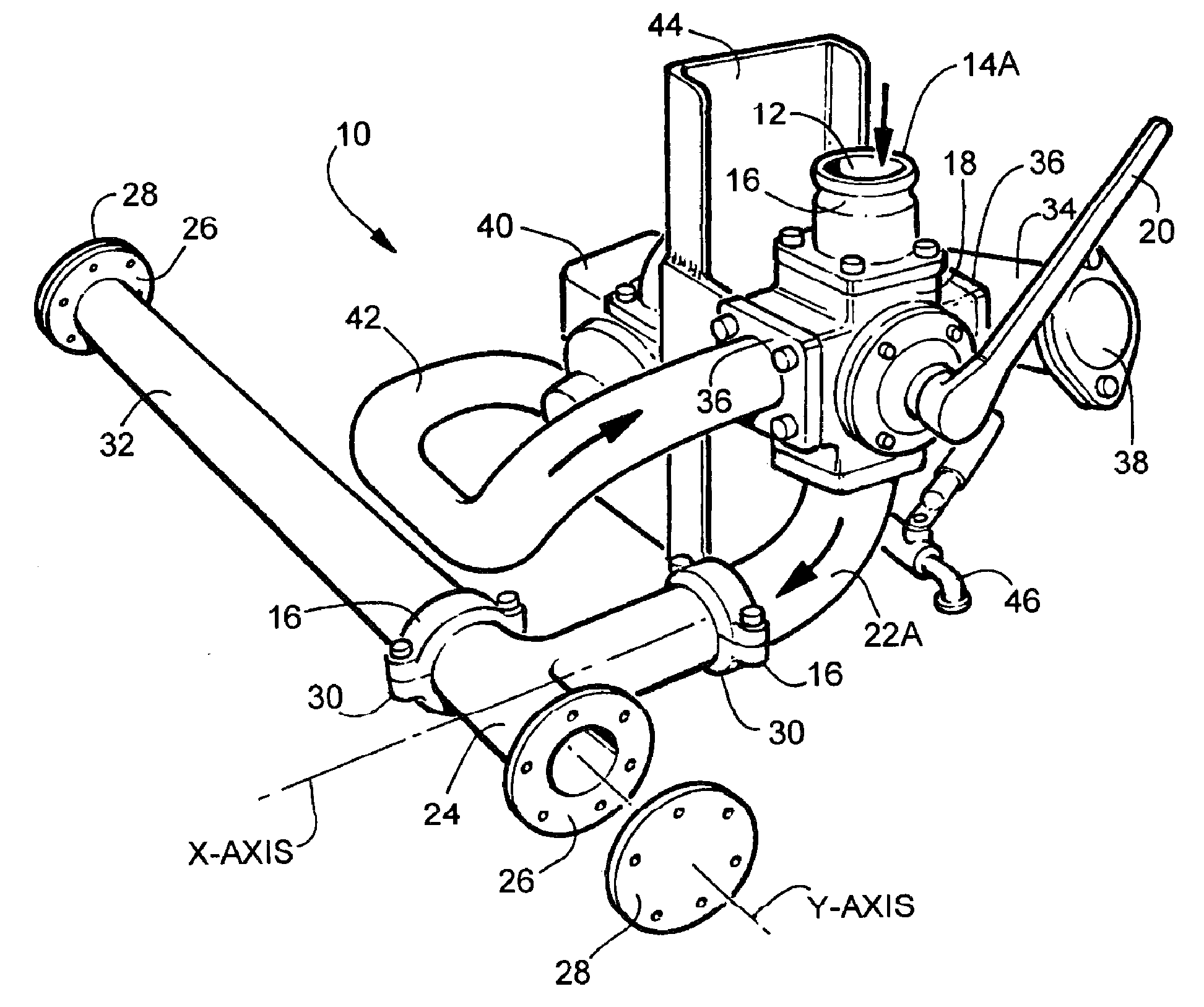
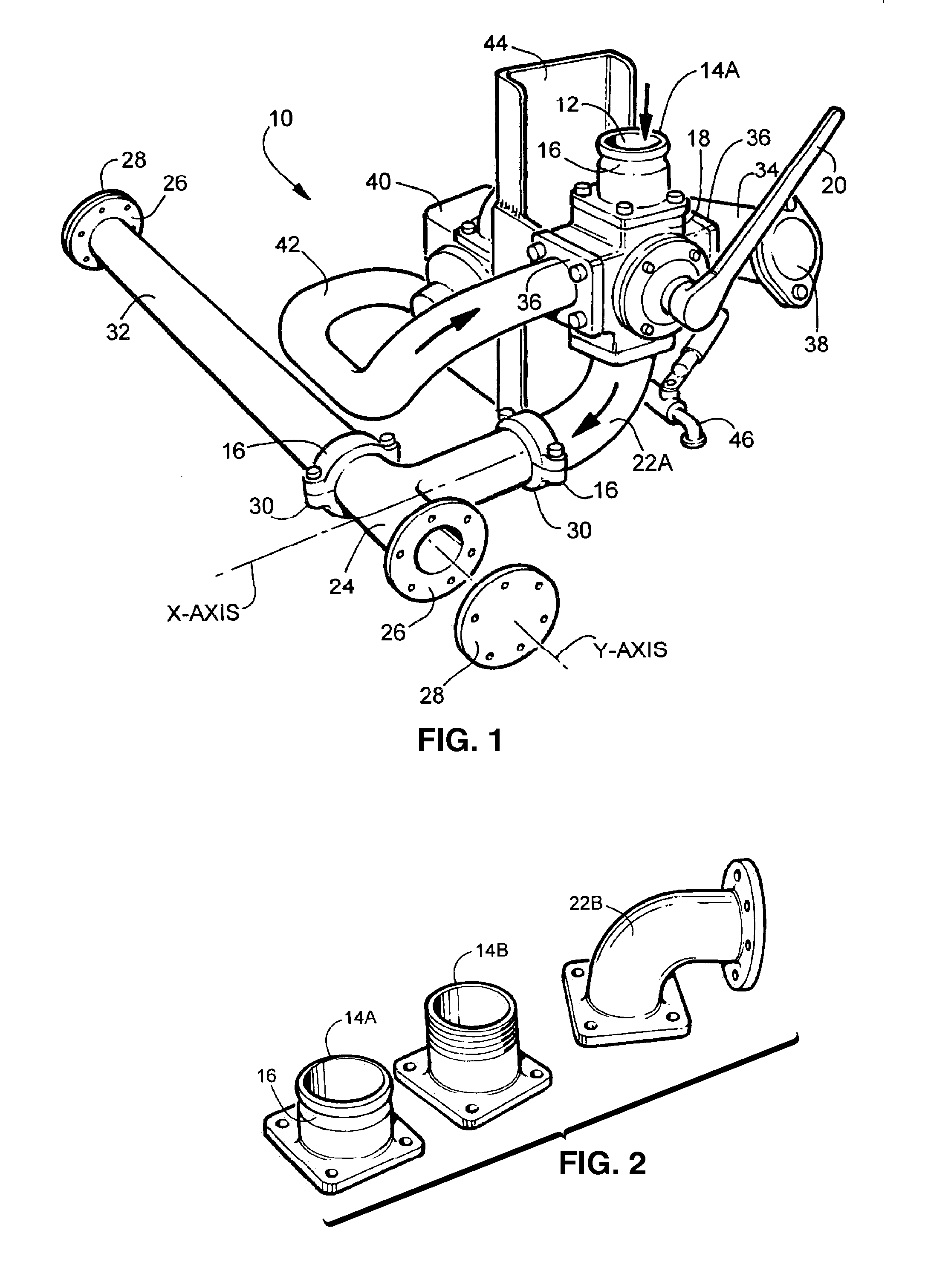
[0087] There is seen in FIG. 1 a perspective view of the left side of the manual bulk liquid pump control and distribution system 10. This view illustrates the directional discharge flow of the bulk liquid with arrows having the intake orifice 12 in the flanged coupling 14A with a flexible victaulic coupling means 16 at the top of the flow reversing two-way valve 18. The flow reversing two-way valve 18 is shown with the valve handle 20 to the right in the discharge position. At the bottom of the flow reversing two-way valve 18, the discharge orifice connects to a 90-degree elbow 22 co...


PUM

PropertyMeasurementUnit
diameteraaaaaaaaaa
pressureaaaaaaaaaa
flow rateaaaaaaaaaa

Abstract

The present invention is a pump control and distribution system consisting of a pump and reversing flow control valve with a single-handle to control flow direction and flow rate of a liquid. The system can be operated at a rate of 0 to 300 gallons per minute and the flow reversed or stopped with a single motion of the operating handle. The flow rate of the liquid can be precisely controlled in either direction, along with the liquid pressure. This allows the use of a constant speed pump turning in one direction and gives the operator the ability to control the product transfer regardless of viscosity or volume. A purge valve connected to the outlet of the pump is used to remove substantially all retained liquid in the system after transfer of liquid is complete. The system can be mounted to a vehicle for delivery of bulk liquids.

Description

CROSS-REFERENCE TO RELATED APPLICATIONS [0001] This application is a continuation-in-part of U.S. patent application Ser. No. 11 / 534,945 filed on Sep. 25, 2006, incorporated herein by reference in its entirety, which is a continuation of U.S. patent application Ser. No. 10 / 893,053 filed on Jul. 16, 2004, now U.S. Pat. No. 7,124,792, incorporated herein by reference in its entirety. [0002] This application is also related to PCT international application serial number PCT / US05 / 25363 filed on Jul. 18, 2005, and published as WO 2006 / 20175 on Feb. 12, 2006, incorporated herein by reference in its entirety.STATEMENT REGARDING FEDERALLY SPONSORED RESEARCH OR DEVELOPMENT [0003] Not Applicable INCORPORATION-BY-REFERENCE OF MATERIAL SUBMITTED ON A COMPACT DISC [0004] Not Applicable NOTICE OF MATERIAL SUBJECT TO COPYRIGHT PROTECTION [0005] A portion of the material in this patent document is subject to copyright protection under the copyright laws of the United States and of other countries. ...

Claims


Application Information

Patent Timeline
Patent Type & Authority Applications(United States)
IPC IPC(8): B65B1/04B65B3/04
CPCF04B49/22F04B53/16F04D15/0005F04D15/0016Y10T137/3109Y10T137/85994
Inventor PALMER, DAVID
Owner SAFETY PUMPING SYST
Why Eureka
Try Eureka