Optical code reading system and method for processing multiple resolution representations of an image

a reading system and image technology, applied in the field of image processing, can solve the problems of significantly affecting the performance of any imager, and the decoding time is too slow for high-performance bar code reading applications, so as to achieve the effect of improving performan

Active Publication Date: 2007-05-10
SYMBOL TECH LLC
View PDF11 Cites 46 Cited by
  • Summary
  • Abstract
  • Description
  • Claims
  • Application Information

AI Technical Summary

Benefits of technology

[0012] Another aspect of the present disclosure is to provide an optical code reading system having a variable resolution imaging sensor programmed to generate a low resolution image, thereby requiring less time to transfer the image to at least one processor or decoder for decoding.
[0014] Another aspect of the present disclosure is to provide an optical code reading system with at least one variable resolution imaging sensor and incorporating all of the features and methodologies recited in the aspects identified above, thereby having improved performance, a high-speed auto-exposure system, a high-speed decode time for reading and decoding low- and high-density bar codes, an optical zoom system having no moveable parts, and other benefits and advantages.
[0017] Additionally, the present disclosure relates to an optical code reading system with at least one variable resolution imaging sensor and incorporating all of the features and methodologies recited above, thereby having improved performance, a high-speed auto-exposure system, a high-speed decode time for reading and decoding low- and high-density bar codes, an optical zoom system having no moveable parts, and other benefits and advantages.

Problems solved by technology

This amount of time can substantially slow down the first-read times for an imager or imaging engine in an optical code reading system and significantly affect any imager's performance.
These decode times are too slow for high performance bar code reading applications.

Method used


Image

  • Optical code reading system and method for processing multiple resolution representations of an image
  • Optical code reading system and method for processing multiple resolution representations of an image
  • Optical code reading system and method for processing multiple resolution representations of an image

Examples


Embodiment Construction

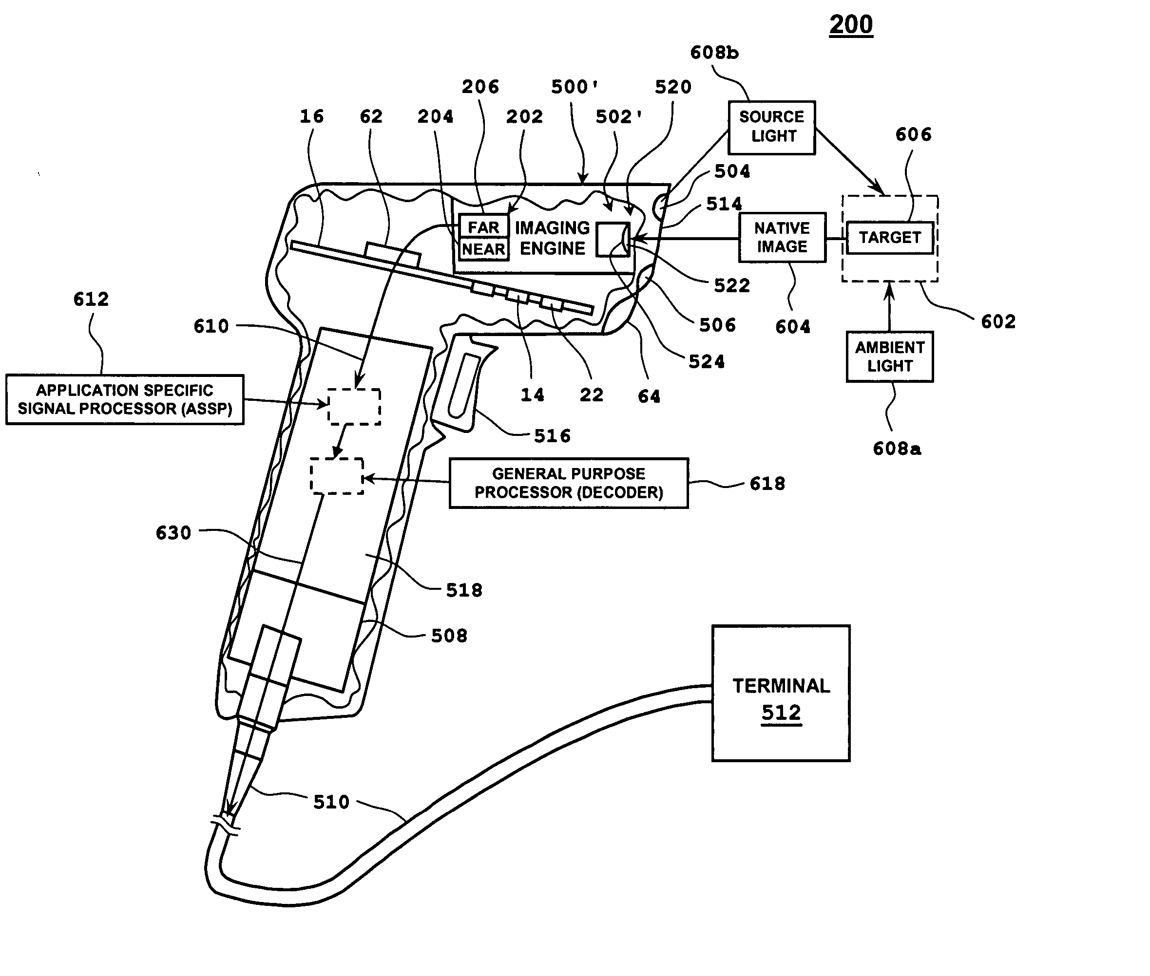
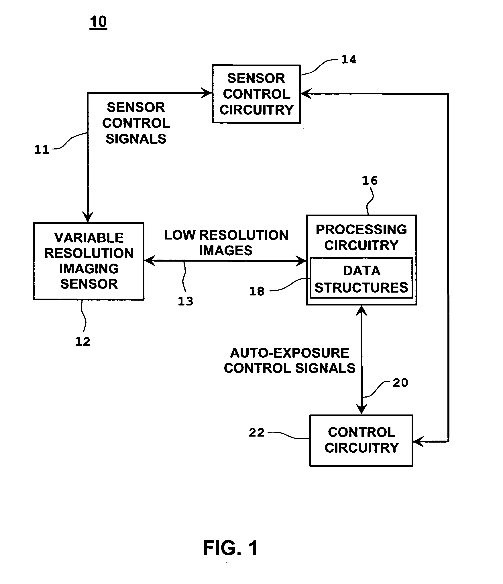
[0042] With reference to FIG. 1, there is shown a schematic illustration of an auto-exposure system for use with a variable resolution imaging sensor of an optical code reading system in accordance with the present disclosure. Even though the present disclosure is described herein with reference to an optical code reading system for imaging and decoding optical codes, such as bar codes, the aspects and features described herein can be incorporated in other systems, such as a video camera system, a digital camera system, etc.

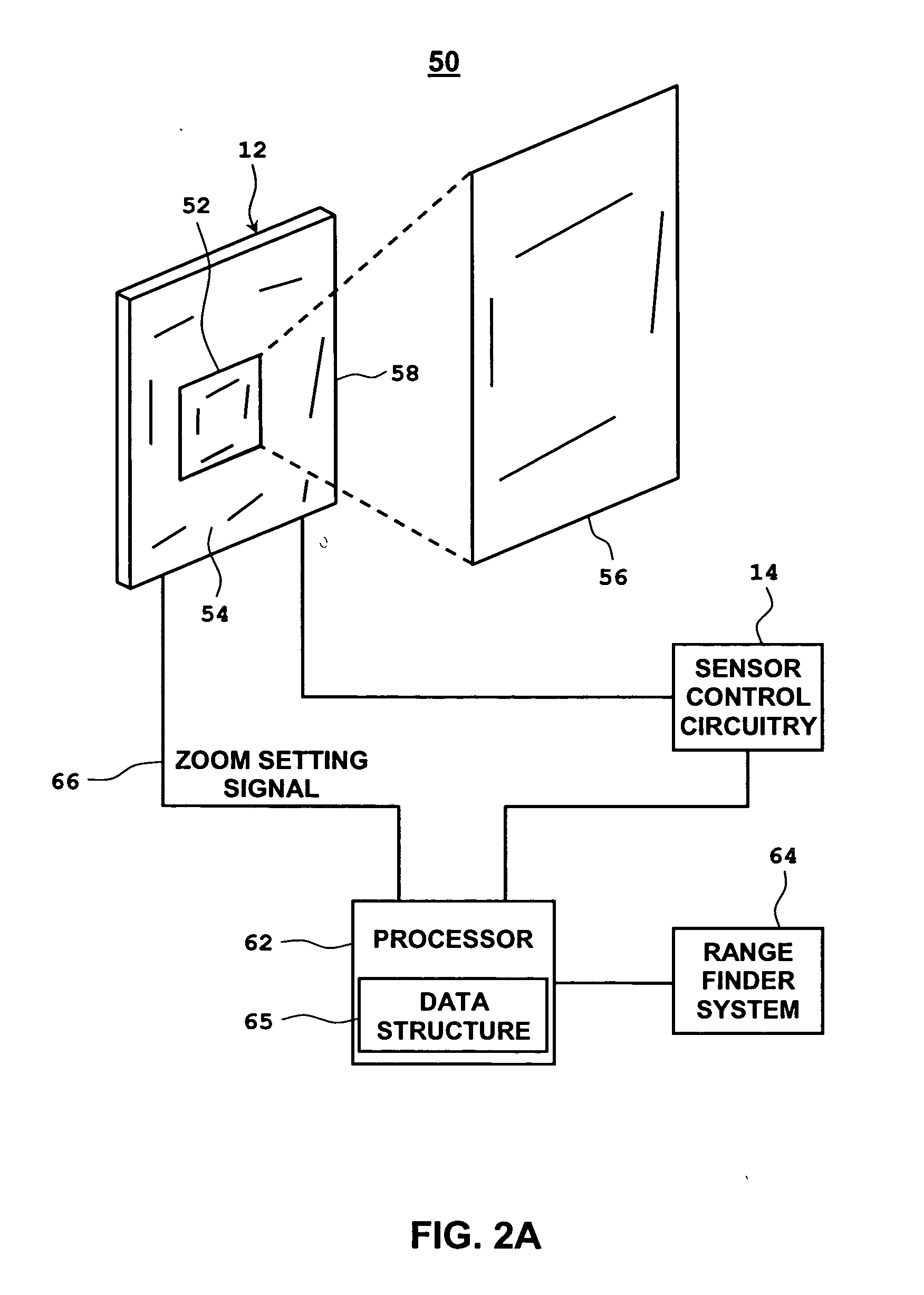
[0043] The auto-exposure system 10 of the optical code reading system 200 (FIG. 4) makes use of a variable resolution imaging sensor 12 which is capable of generating and outputting images having at least two different resolutions, i.e., a low and a high resolution. The variable resolution imaging sensor 12 can also be capable of generating and outputting images having a plurality of resolutions ranging from low to high. The sensor 12 can be a CCD, CMOS, or othe...


PUM


Abstract

An optical code reading system includes an imaging engine having an illuminating assembly for illuminating a potential target area; an imaging assembly including an imaging sensor for acquiring a native image of a potential target area; and circuitry for converting the native image of a potential target area to a data signal and outputting the data signal. The data signal includes potential target area data indicative of low and high resolution representations of the native image; and at least one processor that includes means for receiving the data signal and separating the potential target area data included within the data signal into at least first and second groups of pixels indicative of the low and high resolution representations. The processor may also receive intermediate resolution representations. A corresponding imaging engine and processors capable of implementing the method of separating the high, low and intermediate resolution representations are also disclosed.

Description

PRIORITY [0001] This application is a continuation in part (CIP) of U.S. patent application Ser. No. 10 / 891,851 by Joseph et al., entitled “OPTICAL CODE READING SYSTEM AND METHOD USING A VARIABLE RESOLUTION IMAGING SENSOR,” filed on Jul. 15, 2004.BACKGROUND [0002] 1. Technical Field [0003] The present disclosure relates to the field of imaging. [0004] 2. Description of the Related Art [0005] CCD or CMOS imaging sensors are typically used in imaging devices, such as optical code reading devices for reading and decoding optical codes, such as bar codes. These sensors generally have an imaging pixel array having a plurality of photosensitive elements or pixels for capturing an image. Each pixel of the pixel array has a fixed aspect ratio (i.e., width-to-height). The aspect ratio of the pixels in an optical code reading device is generally determined by the type and / or density of the images, e.g., bar codes, to be read by the imaging device. [0006] Due to the limited dynamic range of CC...

Claims


Application Information

Patent Timeline
Patent Type & Authority Applications(United States)
IPC IPC(8): G06K7/10
CPCG06K7/10722H04N3/1562H04N5/2351H04N23/71H04N25/42H04N25/443
Inventor CARLSON, BRADLEYJOSEPH, EUGENE
Owner SYMBOL TECH LLC
Why Eureka
Try Eureka