Alarm system for detecting excess temperature in electrical wiring

a technology of electrical wiring and alarm system, which is applied in the direction of fire alarms, fire alarm electric actuators, instruments, etc., can solve the problems of circuit breakers not being prevented, faulty wiring generating heat, and many fires, so as to enhance the performance of radio lines, add speed and accuracy to each bit of data, and the appearance is extremely simple

Inactive Publication Date: 2007-05-10
LUMINESCENCE TECH
View PDF9 Cites 8 Cited by
  • Summary
  • Abstract
  • Description
  • Claims
  • Application Information

AI Technical Summary

Benefits of technology

[0011] Another great advantage is that the apparatus is extremely simple, both in the elements and components making up the system, and the installation thereof. This last advantage includes the fact that the connection between the individual location or residence, and the fire station, consists of only a single telephone line, with only the usual operating appurtenances.
[0012] The system is controlled by a microprocessor located in a base unit. An L.C.D. panel located on the base unit enables the user to locate the malfunctioning box. A random access memory stores all data. As an alternative to having each sensor hardwired to the central location, a thermistor or group of thermistors may be connected to a transmitter. The transmitter communicates with the base station using UHF radio signals. The radio datalink allows the unit to perform at long ranges.
[0013] Digital and line filters enhance the performance of the radio line. Using a Digital to Analog converter adds speed and accuracy to each bit of data. When the data is displayed on the L.C.D. screen, it shows the malfunctioning box in two dimensions.

Problems solved by technology

It is well known that many fires are caused by failures in electrical wiring.
Frequently, faulty wiring will generate heat long before the ignition temperature of the surrounding structure is reached.
Circuit breakers do not prevent a fire in this situation because the current flowing through the fault is not great enough to trip a standard breaker.
Furthermore, conventional fire detection systems are also inadequate because they only detect the byproducts of combustion, such as smoke and intense heat.
The localized heat rise in failing wiring typically goes undetected until after a fire has started.

Method used


Image

  • Alarm system for detecting excess temperature in electrical wiring
  • Alarm system for detecting excess temperature in electrical wiring
  • Alarm system for detecting excess temperature in electrical wiring

Examples


Embodiment Construction

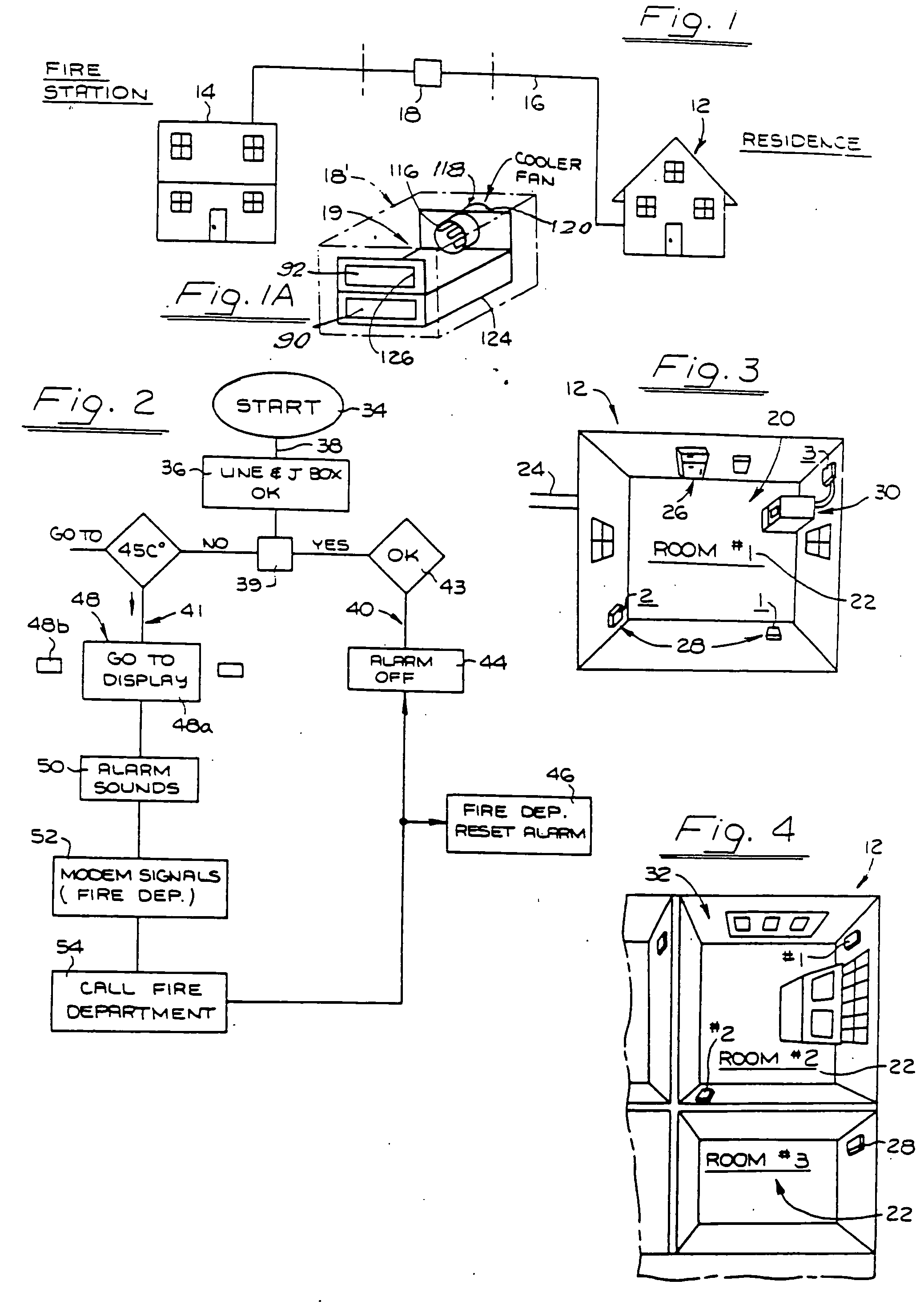
[0040] Attention is directed first to FIG. 1 representing the overall arrangement of use of the fire alarm system, where a residence is indicated at 12 and the central station at 14 which y be a fire station, as in the present instance. These locations, i.e., residence and fire station, are interconnected y a single telephone line 16 constituting the only necessaconnection therebetween. Various components are indicated at utilized in the telephone line, including any that are necesily in the telephone central station. The single telephone line 16 is utilized in a manner presently known, such as in use th the well known FAX machines.

[0041]FIGS. 1, 3, and 4 indicate or show various pions of the electrical system in the house, and telephone compts, and it will be appreciated that they are very extensive ically and spatially, and that the components of the device he present invention are contained effectively entirely ihe package represented in FIG. 1a. As indicated above, in electrica...


PUM


Abstract

The system includes a sensor for each junction box in the building to be guarded, e.g., the residence, and a display panel showing the temperature of any junction box that is heated above the danger point. Another display panel shows the name of the resident and address of the residence, and the location of the heated junction box by room number and junction box number and the shape of the junction box. A plurality of residences are connected with a central station, such as a fire station, by a single telephone line to each residence. A single processing unit is located in each residence, and a single such unit is located in the central display station. A display panel is located in the central station identical with each display in a residence. The central station is provided with a single processing unit responsive to actuating of any and each of the processing units in the residences, the central station having a modem operable for receiving signals from the processing units in the units and processing them according to the respective processing units in the residences. The system also includes rotating extinguisher heads which rotate towards the source of any dangerous heat an extinguish the fire.

Description

CROSS-REFERENCE TO RELATED APPLICATION [0001] This application is a continuation of U.S. patent application Ser. No. 08 / 250,095, filed Apr. 26, 1994, which is a continuation-in-part of U.S. patent application Ser. No. 07 / 907,185, filed Jul. 1, 1992, now abandoned. Each of these related applications is incorporated herein by reference in its entirety.STATEMENT REGARDING FEDERALLY SPONSORED RESEARCH OR DEVELOPMENT [0002] Not applicable. BACKGROUND OF THE INVENTION [0003] It is well known that many fires are caused by failures in electrical wiring. Frequently, faulty wiring will generate heat long before the ignition temperature of the surrounding structure is reached. Circuit breakers do not prevent a fire in this situation because the current flowing through the fault is not great enough to trip a standard breaker. [0004] Furthermore, conventional fire detection systems are also inadequate because they only detect the byproducts of combustion, such as smoke and intense heat. The loca...

Claims


Application Information

Patent Timeline
Patent Type & Authority Applications(United States)
IPC IPC(8): G08B17/00G08B21/00G08B29/00G08B25/08G08B25/10
CPCA62C3/16G08B17/06G08B21/185G08B25/08G08B25/10
Inventor BOYDEN, DAVID
Owner LUMINESCENCE TECH
Why Eureka
Try Eureka