Virtual space image display method, apparatus, virtual space image display program, and recording medium

a virtual space image and display method technology, applied in computing, maps/plans/charts, instruments, etc., can solve the problems of increasing the load of the apparatus including the cpu for creating the distant view image, and the speedup of the processing speed cannot be avoided, so as to avoid the increase of the load of the apparatus including the cpu and enhance the processing speed

Inactive Publication Date: 2007-05-10
SONY CORP
View PDF62 Cites 45 Cited by
  • Summary
  • Abstract
  • Description
  • Claims
  • Application Information

AI Technical Summary

Benefits of technology

[0010] In view of the above circumstances, it is desirable to provide a virtual space image display method, apparatus, a virtual space image display program and a recording medium, in which an increase in the load of an apparatus including a CPU is avoided at a time when a distant view image close to an actual landscape, which should be actually seen on the background of a near view image, is displayed, and a realistic map image based on a perspective drawing method can be drawn without enhancing the processing speed.
[0013] A virtual space image display program according to another embodiment of the invention is a virtual space image display program for causing a computer to draw and display, when viewing is made in an arbitrary direction from a point of interest on map data, a drawing object on the map data positioned in the direction on the basis of three-dimensional map data of the drawing object as a map image based on a perspective drawing method, and causes the computer to execute the processes of holding three-dimensional map data of drawing objects in respective division areas, which are obtained by dividing the map data into specified areas, in a recording medium for the respective division areas, holding distant view images of drawing objects for a distant view in respective directions on the map data, which are obtained when surroundings are viewed from an inside of the division area, in the recording medium while the distant view images are made to correspond to the division area and the directions, acquiring, by point-of-interest acquisition means, position information of the point of interest and sight line direction information concerning a sight line direction or a traveling direction at the point of interest, retrieving, by neighboring map data retrieval means, three-dimensional map data of a drawing object for a near view positioned in the sight line direction or the traveling direction, including a drawing object in the division area where the point of interest exists, from the three-dimensional map data held in the recording medium on the basis of the acquired position information of the point of interest and the sight line direction information, performing, by real-time rendering means, a rendering processing on the retrieved three-dimensional map data to convert the drawing object for the near view positioned in the sight line direction or the traveling direction into a map image based on the perspective drawing method, retrieving, by distant view data retrieval means, a distant view image obtained when viewing is made in the sight line direction or the traveling direction from the inside of the division area where the point of interest exists, from the distant view images held in the recording medium on the basis of the acquired position information of the point of interest and the sight line direction information, and overwriting, by combining means, the retrieved distant view image with the drawing object for the near view converted into the map image based on the perspective drawing method to combine them, and drawing and displaying them as a map image based on the perspective drawing method in the sight line direction or the traveling direction at the point of interest.
[0015] According to the embodiment of the invention, since the distant view image is previously held in the recording medium, it is unnecessary to perform the rendering processing at the time when the distant view image is drawn, it has only to be retrieved and read out from the recording medium, and there is an effect that the virtual space image display method / apparatus, the virtual space image display program and the recording medium can be provided in which an increase in the load of the apparatus including the CPU can be avoided as compared with the case where the rendering processing is performed each time the position of the point of interest, the sight line direction or the traveling direction is changed and the distant view image is drawn.
[0016] Besides, since the distant view image is created for each of the division areas so as to have a size corresponding to the distance between the division area and the drawing object for the distant view, there is an effect that the virtual space image display method / apparatus, the virtual space image display program and the recording medium can be provided in which the map image which is based on the perspective drawing method and in which the realistic distant view image is drawn on the background can be drawn without enhancing the processing speed.

Problems solved by technology

Thus, there has been a problem that in order to perform the realistic image display in which the distant view image, such as the building or mountain, which should be actually seen on the background of the near view image is displayed, the load in the apparatus including a CPU (Central Processing Unit) for creating the distant view image is increased and the speedup of the processing speed can not be avoided.

Method used


Image

  • Virtual space image display method, apparatus, virtual space image display program, and recording medium
  • Virtual space image display method, apparatus, virtual space image display program, and recording medium
  • Virtual space image display method, apparatus, virtual space image display program, and recording medium

Examples


embodiment 1

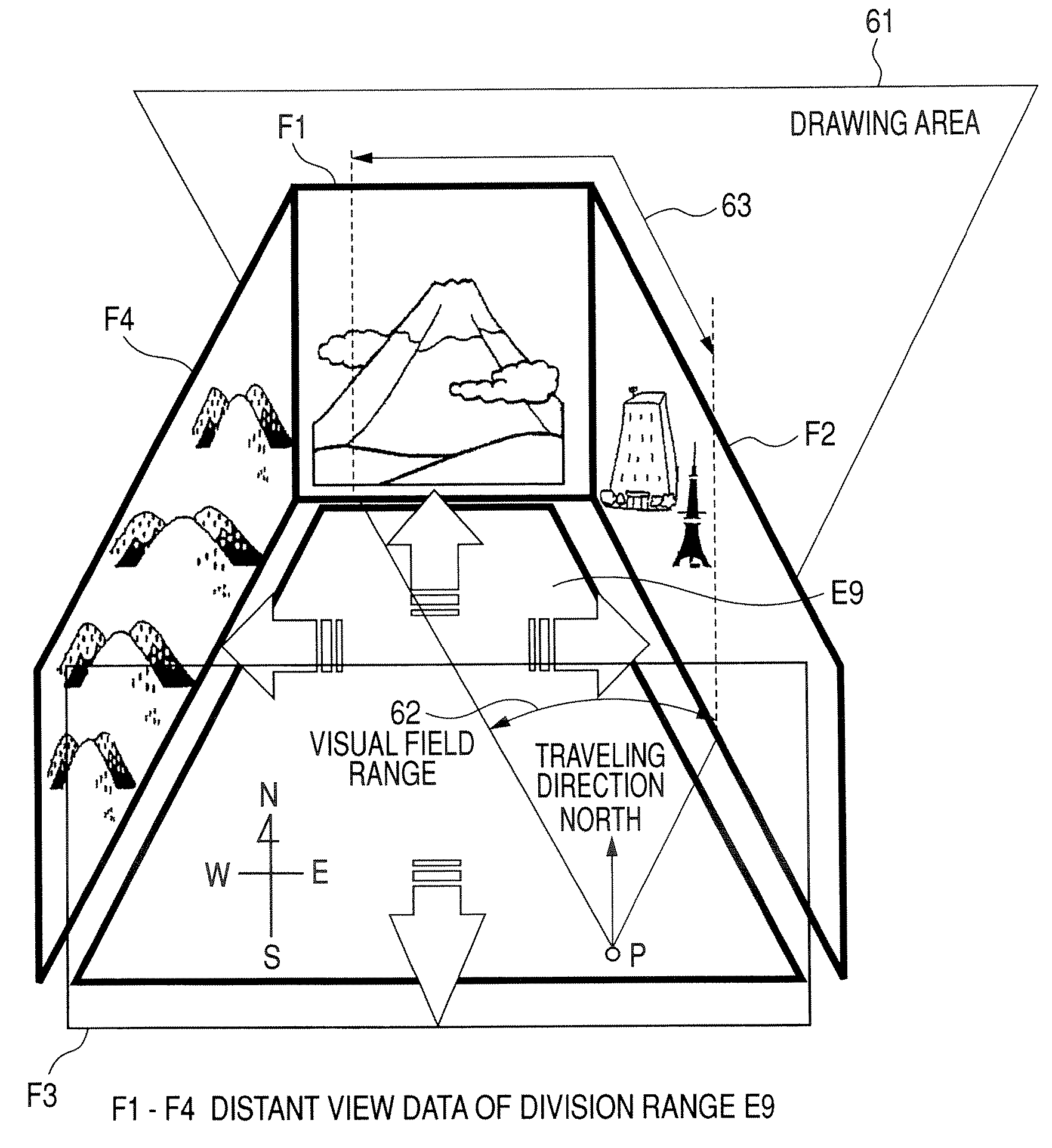
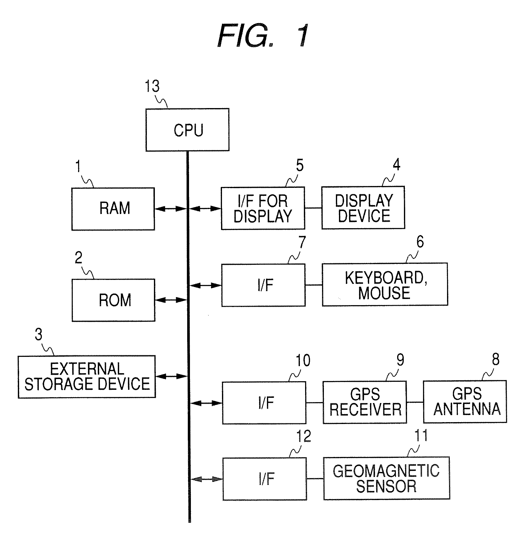
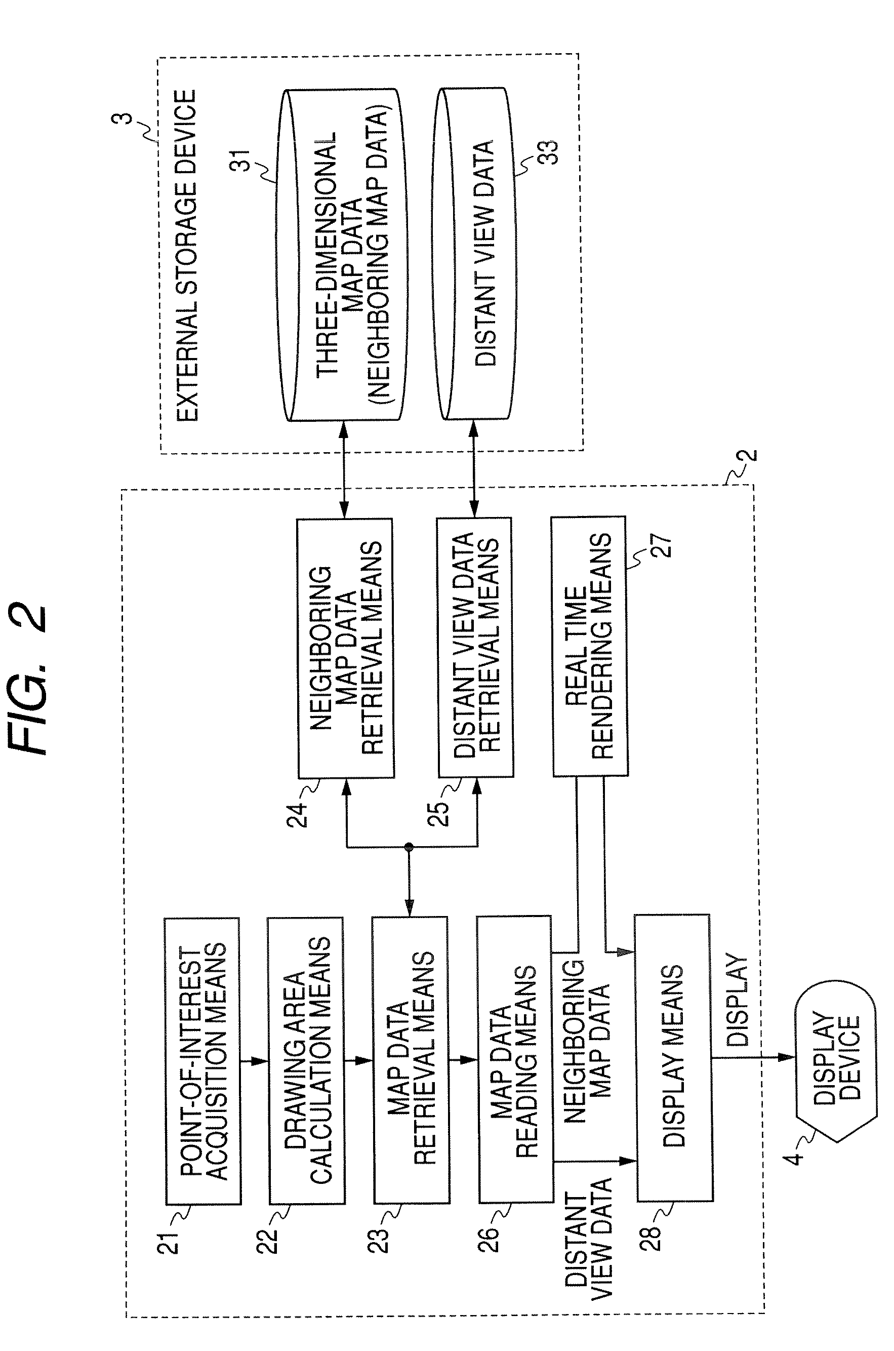
[0034]FIG. 1 is a block diagram showing a hardware structure of a virtual space image display apparatus to which a virtual space image display method of embodiment 1 is applied. This virtual space image display apparatus includes a RAM (Random Access Memory) 1, a ROM (Read Only Memory) 2, an external storage device (recording medium) 3 which previously stores three-dimensional map data including information indicating positions and forms of constructions, such as roads and buildings, of map data divided into specified division areas, and distant view data indicating distant view images for the respective division areas and having been previously subjected to a rendering processing, a display device 4, a display interface 5 for transmitting / receiving various signals to display map images based on a perspective drawing method to / from the display device 4, an input device 6 including a keyboard, a mouse or an operation pad for variously operating the virtual space image display apparat...

embodiment 2

[0097]FIG. 12 is a block diagram showing a structure of an in-vehicle navigation apparatus to which the virtual space image display method / apparatus, or the virtual space image display program described in the embodiment 1 is applied. In FIG. 12, portions having the same or like functions to those of FIG. 1 are denoted by the same reference numerals.

[0098] The in-vehicle navigation apparatus includes a RAM 1, a ROM 2, and an external storage device 3 that previously stores three-dimensional map data including information indicating the positions and forms of constructions, such as roads and buildings, of map data divided into specified division areas, and distant view data which are distant view images for the respective division areas and are previously subjected to the rendering processing.

[0099] Besides, the in-vehicle navigation apparatus includes a display device 4, an interface 5 for display through which a CPU 13 transmits / receives various signals for displaying map images ...

embodiment 3

[0107]FIG. 13 is a block diagram showing a structure of a portable navigation apparatus to which the virtual space image display method / apparatus, or the virtual space image display program described in the embodiment 1 is applied. In FIG. 13, portions having the same or like functions to those of FIG. 12 are denoted by the same reference numerals and their description will be omitted.

[0108] Since the portable navigation apparatus of the embodiment 3 is used while the user carries it, the vehicle sensor 77 is not provided unlike the in-vehicle navigation apparatus.

[0109] In this portable navigation apparatus, the point-of-interest acquisition means 21 of FIG. 2 realizes a function to acquire information of the point of interest as the present position and the sight line direction or traveling direction based on various information, such as latitude and longitude information detected based on a GPS signal received by a GPS receiver 9 from a GPS satellite, an output signal of a gyro...


PUM


Abstract

Three-dimensional map data of drawing objects in respective division areas and distant view images in respective directions on map data, which are obtained when viewing is made from insides of the respective division areas, are held in a recording medium, three-dimensional map data of a drawing object for a near view positioned in a sight line direction at a point of interest is retrieved from the three-dimensional map data based on position information of the point of interest and sight line direction information, and is converted into a map image based on a perspective drawing method. A distant view image obtained in the sight line direction is retrieved from the distant view images held in the recording medium based on the position information of the point of interest and the sight line direction information, and the retrieved distant view image is overwritten with the map image for the near view to combine them.

Description

CROSS REFERENCE TO RELATED APPLICATIONS [0001] The present invention contains subject matter related to Japanese Patent Application JP 2005-323757 filed in the Japanese Patent Office on Nov. 8, 2005, the entire contents of which being incorporated herein by reference. BACKGROUND OF THE INVENTION [0002] 1. Field of the Invention [0003] The present invention relates to a virtual space image display method, apparatus, a virtual space image display program and a recording medium, that enables drawing of a map image which is close to an actual landscape and is based on a perspective drawing method. [0004] 2. Background Art [0005] In related art, when a map image based on a perspective drawing method is drawn, it becomes necessary to perform a processing of extracting a building as a drawing object from map data. As an extraction method of the building as the drawing object, a specific region from a present position or a point of interest is made the drawing object, and data of the buildi...

Claims


Application Information

Patent Timeline
Patent Type & Authority Applications(United States)
IPC IPC(8): G06T15/00G06T17/05G09B29/00
CPCG06T17/05G06T19/00G06T15/20
Inventor SUZUNO, SATOSHIOKUDA, SHIZUEKODA, NATSUOITO, JUNPEI
Owner SONY CORP
Why Eureka
Try Eureka