Motor control system

a technology of motor control and control system, which is applied in the direction of motor/generator/converter stopper, emergency protective arrangement responsive to undesired changes, dynamo-electric converter control, etc., can solve the problems of increasing the size of the entire system and consuming the electric power of the vehicle battery, and achieve the effect of reducing the electric power consumption of the battery

Active Publication Date: 2007-05-10
DENSO CORP
View PDF13 Cites 17 Cited by
  • Summary
  • Abstract
  • Description
  • Claims
  • Application Information

AI Technical Summary

Benefits of technology

[0009] The present invention addresses the above disadvantages. Thus, it is an objective of the present invention to provide a motor control system, which reduces an electric power consumption thereof.

Problems solved by technology

When the motor generates an abnormally high heat, the protective device shuts down an electric circuit to stop supply of the electric power to the motor.
When the protective device is provided to the motor, a size of the motor is disadvantageously increased to cause an increase in a size of the entire system.
Thus, even though the motor is stopped, a microcomputer of the motor control system needs to continuously perform the computing operation of the estimated temperature and thereby always consumes the electric power of the vehicle battery.

Method used


Image

  • Motor control system
  • Motor control system
  • Motor control system

Examples


first embodiment

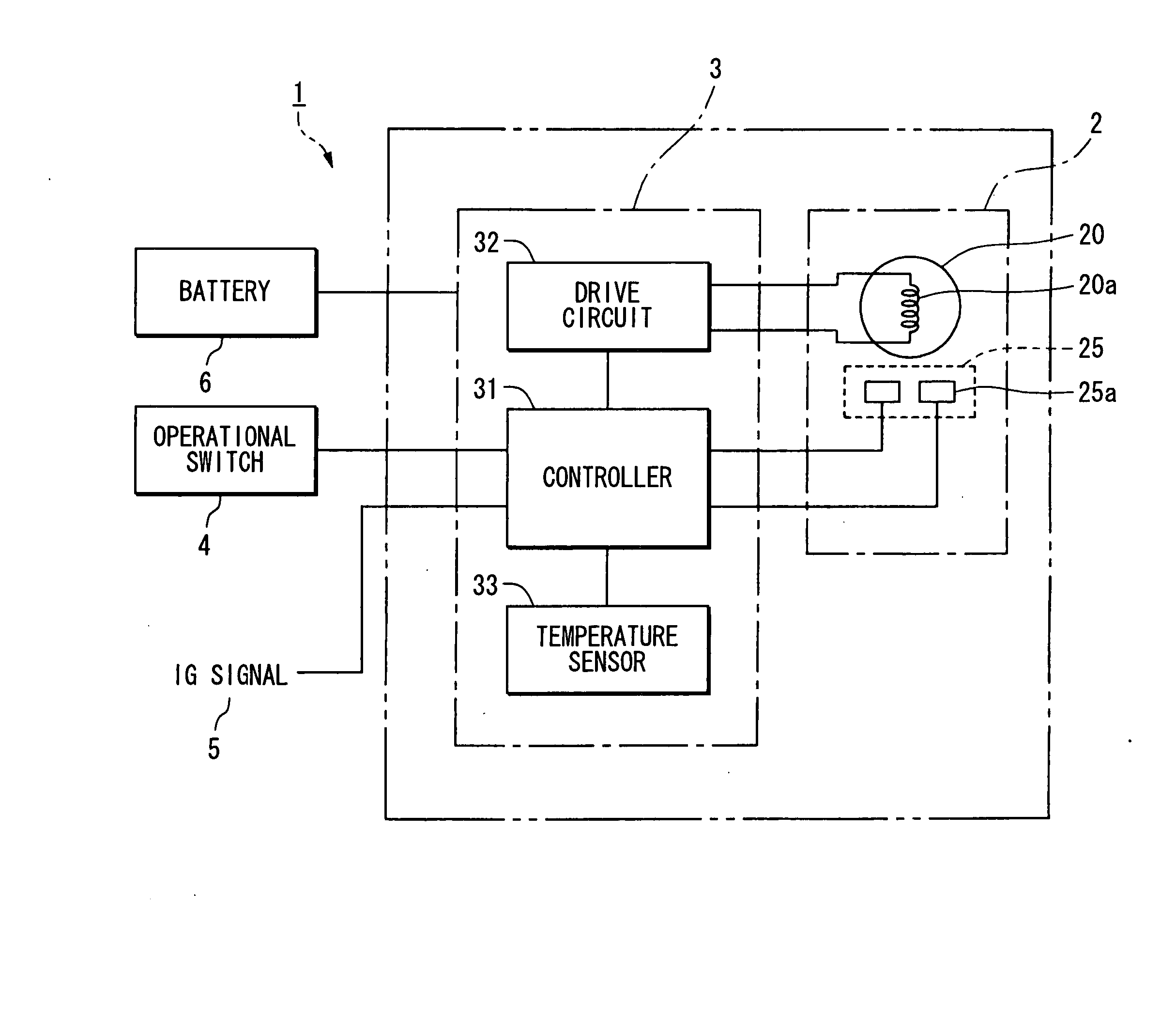
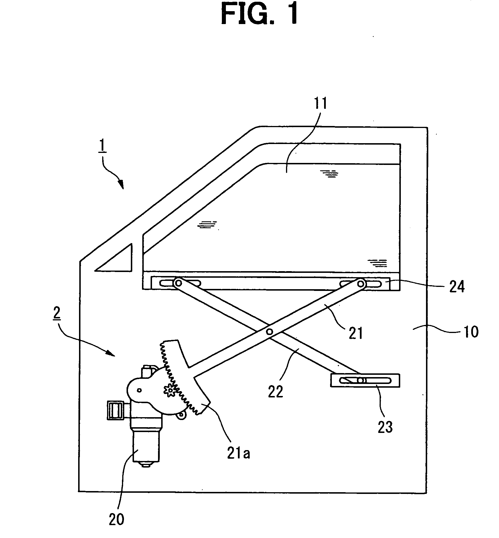
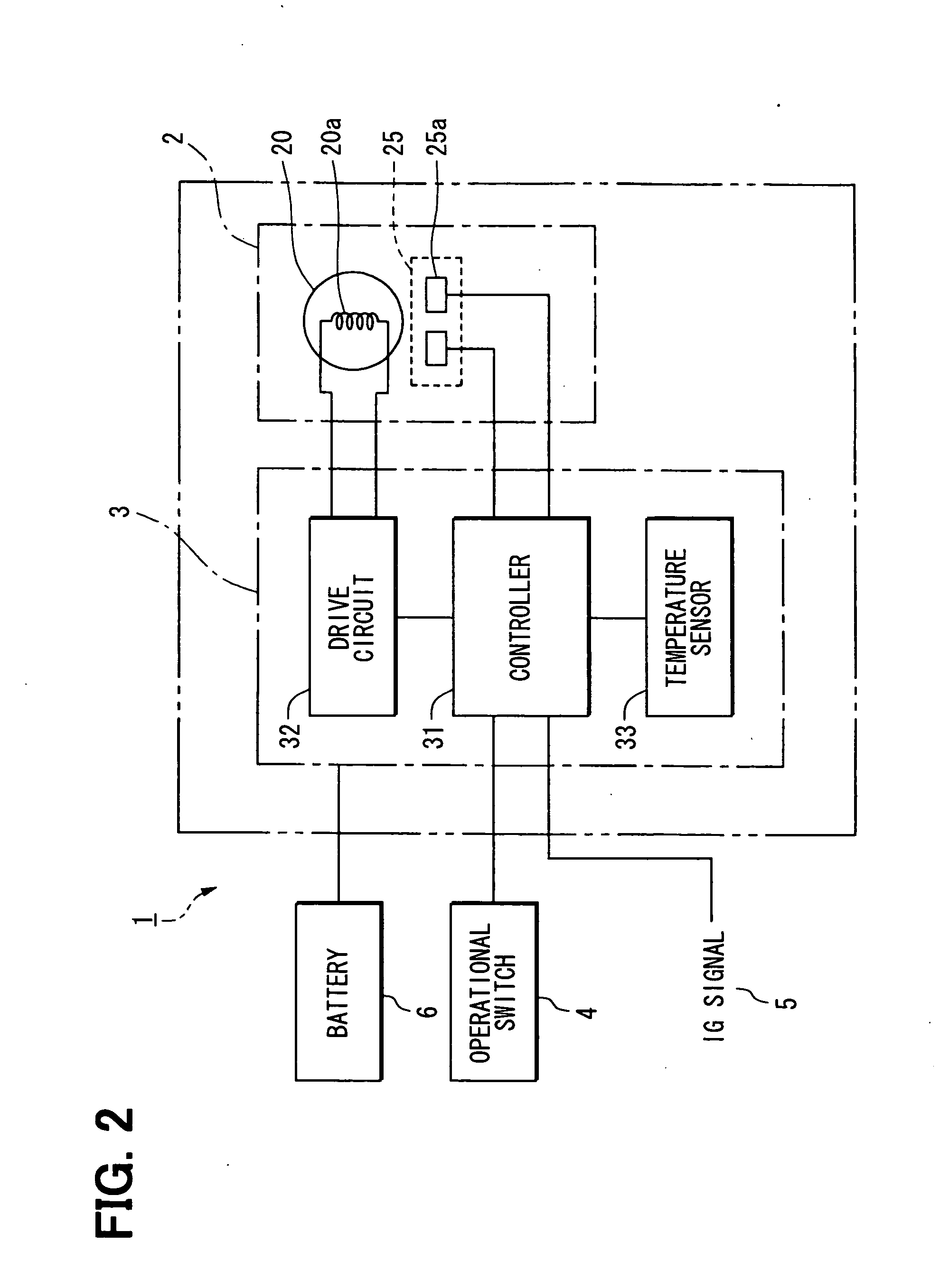
[0022] A first embodiment, in which a motor control system of the present invention is implemented in a vehicle power window system, will be described. FIG. 1 is a descriptive view of the power window system 1 (hereinafter, simply referred to as “system 1”), and FIG. 2 is a diagram showing an electric structure of the system 1. In the system 1, a window glass 11, which is a movable member arranged in a door 10 of a vehicle, is raised and lowered, i.e., closed and opened by an electric motor 20. The system 1 includes a lifting mechanism 2, a control apparatus 3 and a operational switch 4. The lifting mechanism 2 raises and lowers the window glass 11. The control apparatus 3 controls operation of the lifting mechanism 2. A vehicle occupant inputs an operational command for operating the lifting mechanism 2 through the operational switch 4.

[0023] The window glass 11 is vertically driven between a fully closed position (a full up position) and a full open position (a full down position...

second embodiment

[0118] Next, a second embodiment of the present invention will be described. In the following description, the components similar to those of the first embodiment will be indicated with the same numerals and will not be described further for the sake of simplicity.

[0119] In the first embodiment, the condition (the first sleep condition) for changing from the active mode to the first sleep mode is that the predetermined IG signal (the OFF signal), which indicates the state of the ignition switch, is inputted to the controller 31. However, the present invention is not limited to this. For example, the condition (the first sleep condition) for changing from the active mode to the first sleep mode may be set as an elapsed time since the time of stopping the rotation of the motor 20. In the second embodiment, it is determined whether the active mode needs to be changed to the first sleep mode based on the elapsed time since the time of stopping the rotation of the motor 20. The differen...


PUM


Abstract

A controller is operable in one of a plurality of operational modes, which include an estimated temperature computation performing mode for performing computing of an estimated temperature of the motor and an estimated temperature computation non-performing mode for stopping the computing of the estimated temperature of the motor. An operational mode of the controller is changed from the estimated temperature computation performing mode to the estimated temperature computation non-performing mode according to a predetermined condition in a stopped state of the motor.

Description

CROSS REFERENCE TO RELATED APPLICATION [0001] This application is based on and incorporates herein by reference Japanese Patent Application No. 2005-322459 filed on Nov. 7, 2005 and Japanese Patent Application No. 2006-229611 filed on Aug. 25, 2006. BACKGROUND OF THE INVENTION [0002] 1. Field of the Invention [0003] The present invention relates to a motor control system. [0004] 2. Description of Related Art [0005] Previously, a protective device, such as a bimetal or a PTC thermistor, is provided in a housing of a motor to protect the motor from burnout. When the motor generates an abnormally high heat, the protective device shuts down an electric circuit to stop supply of the electric power to the motor. [0006] When the protective device is provided to the motor, a size of the motor is disadvantageously increased to cause an increase in a size of the entire system. Thus, in a motor control system, which is disclosed in Japanese Unexamined Patent Publication No. H11-164472, the abo...

Claims


Application Information

Patent Timeline
Patent Type & Authority Applications(United States)
IPC IPC(8): H02H7/08H02H5/00H02H6/00H02P3/06
CPCH02H6/005H02P29/00H02P29/64
Inventor KOBAYASHI, SHIGERUISHIZU, KEIZO
Owner DENSO CORP
Why Eureka
Try Eureka