
Assembly device for a sidelight light source module and liquid crystal panel

a technology of sidelight light source module and liquid crystal panel, which is applied in the direction of lighting and heating apparatus, planar/plate-like light guides, instruments, etc., can solve the problems of difficult control of the ratio of three colors and the manufacturing process, relative dull white light, and uniformity of mixed light, etc., to achieve superior color rendering and uniformity of transmitted backlight white light, easy control, and easy control

Inactive Publication Date: 2007-05-10
ULTRA BRIGHT LEDS
View PDF0 Cites 19 Cited by
  • Summary
  • Abstract
  • Description
  • Claims
  • Application Information

AI Technical Summary

Benefits of technology

[0009] A primary objective of the present invention is to provide an assembly device for a sidelight light source module and liquid crystal panel that enables easy control of and achieves superior color rendering and uniformity of a transmitted backlight white light.
[0010] Another objective of the present invention is to provide the assembly device for a sidelight light source module and liquid crystal panel with a fluorescent layer used by a backlight source module that is fabricated from induced luminescent material, which enables easy control of the excited light wavelengths, thereby achieving easy control of the color rendering and uniformity of the backlight white light source.
[0011] Yet another objective of the present invention is to provide the assembly device for a sidelight light source module and liquid crystal panel with an easily replaceable light diffuser plate coated with the fluorescent layer, thereby providing renewable functionality.

Problems solved by technology

However, a shortcoming of such a structure is that the ultraviolet light damages current, extensively used epoxy resin structures, causing a problem of final white light attenuation, thereby resulting in a relatively dull white light.
More particularly, a covering layer used in the above cited patent is compounded from red, green and blue color fluorescent substances, which causes another shortcoming in that the ratio of the three colors and the manufacturing process are difficult to control.
However, ratio of the red fluorescent powder and the green fluorescent powder and the manufacturing process are difficult to control, thereby making uniformity of the mixed light (that is, white light) also difficult to control, thereby finally producing poor color rendering of the white light displayed by the liquid crystal panel.
However, the light source lacks a red light spectrum portion, which results in poor color rendering and uniformity of the mixed white light (that is, mixed light) emitted by the fluorescent screen, and is seen by the human eye as impure white light.
However, embodiments of the cited patent are limited to new designs of white light light-emitting diodes, and with regard to application in devices assembled with a liquid crystal panel and backlight module, the cited patent has no extended assembled embodiments.

Method used


Image

  • Assembly device for a sidelight light source module and liquid crystal panel
  • Assembly device for a sidelight light source module and liquid crystal panel
  • Assembly device for a sidelight light source module and liquid crystal panel

Examples


Embodiment Construction

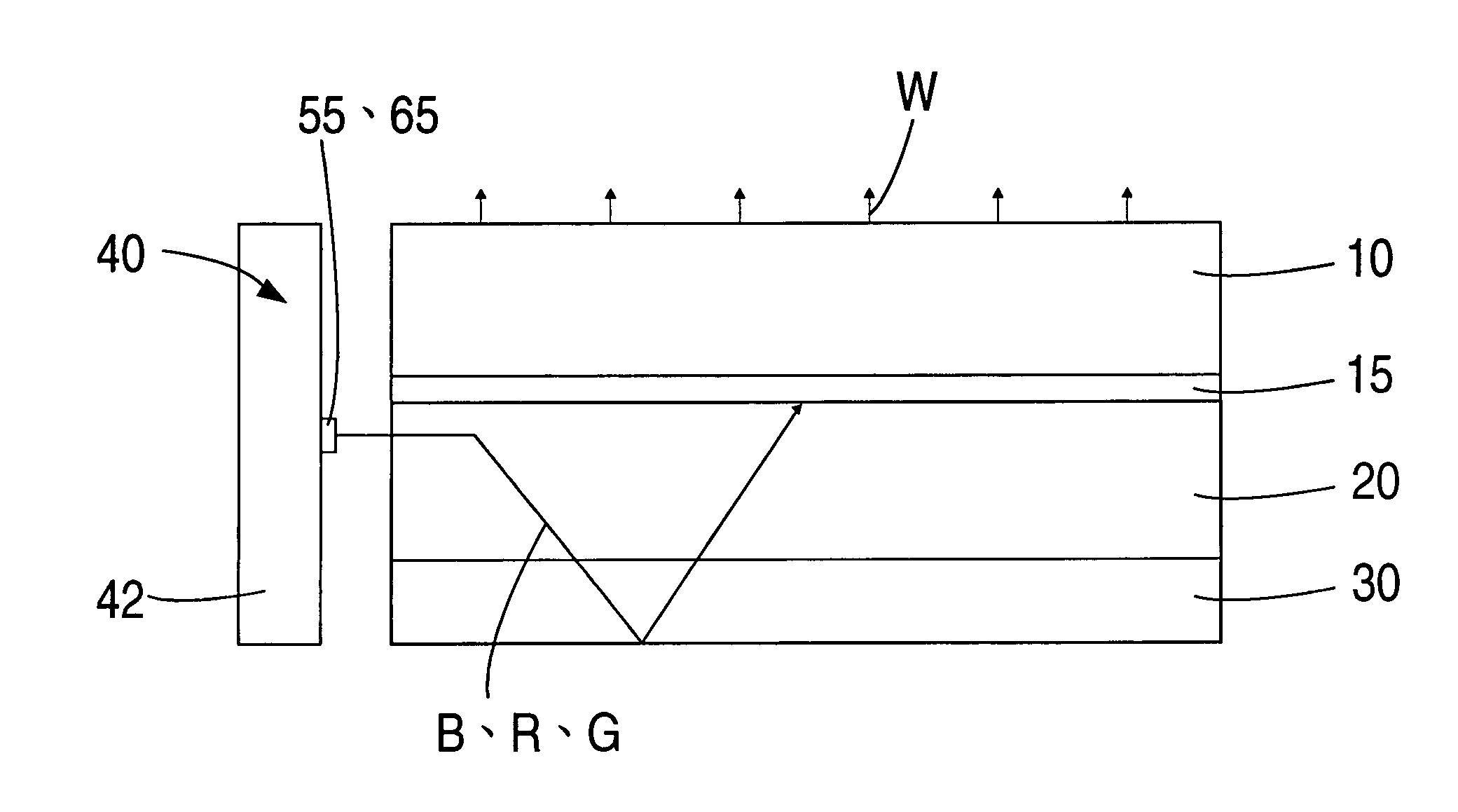
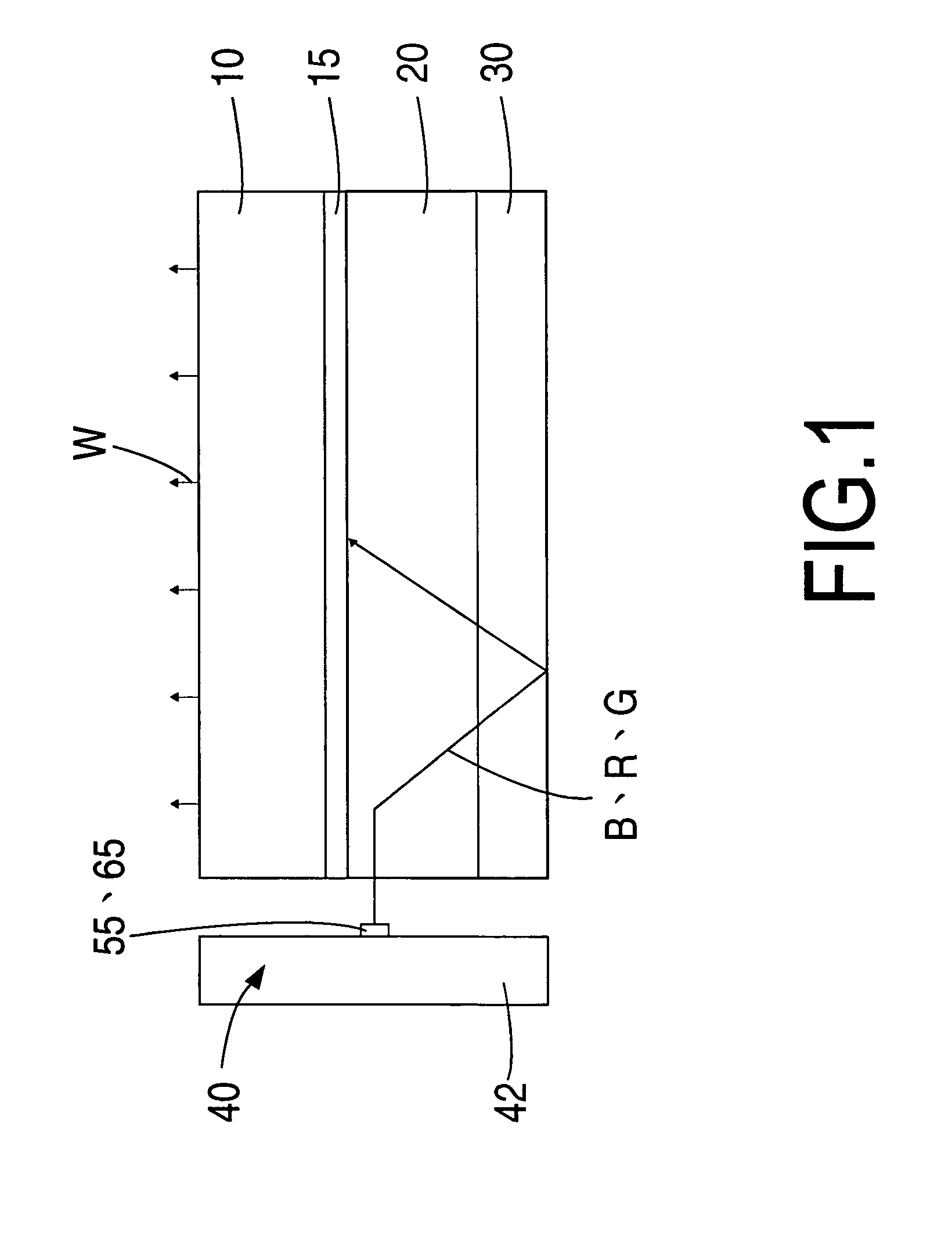
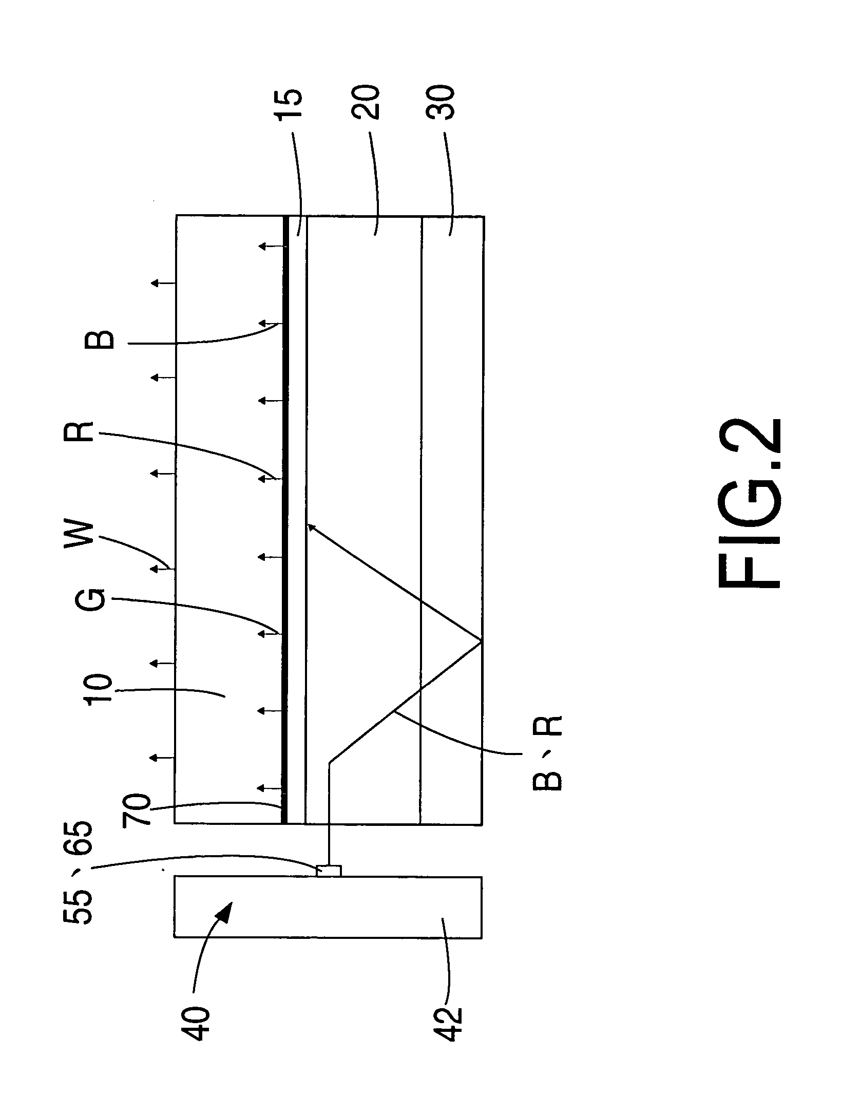
[0028] Referring to FIGS. 1 and 9, the assembly device for a sidelight light source module and liquid crystal panel of the present invention comprises:

[0029] a liquid crystal panel 10;

[0030] a light guide panel 20 positioned below the liquid crystal panel 10;

[0031] a light reflecting plate 30 positioned below the light guide panel 20;

[0032] a light source module 40 installed at a side of the light guide panel 20; wherein the light source module comprises:

[0033] a circuit board 42, on top of which is soldered at least more than one blue light chip 55 that serves as a blue light B light-emitting source and at least more than one red light chip 65 that serves as a red light R light-emitting source, wherein the blue light chips 55 and the red light chips 65 are reciprocally adjacent;

[0034] a luminescence fluorescent layer 70 is positioned on top of the blue light chip 55 and the red light chip 65, wherein the blue light B is primarily used to excite the fluorescent layer 70 and em...


PUM


Abstract

An assembly device for a sidelight light source module and liquid crystal panel, comprising: a liquid crystal panel; a light guide panel; a light reflecting plate; a light source module installed at a side of the light guide panel; wherein the light source module comprises: a circuit board, on top of is soldered blue light chips and red light chips; a luminescence fluorescent layer positioned on top of the blue light chips and the red light chips. Mixed light consisting of the excited light, the blue light and the red light is transmitted out the fluorescent layer and forms a white light that passes through the light guide panel, the light reflecting plate, and is finally transmitted out the liquid crystal panel.

Description

BACKGROUND OF THE INVENTION [0001] (a) Field of the Invention [0002] The present invention relates to an assembly device for a sidelight light source module and liquid crystal panel, which particularly provides a white light backlight source having superior color rendering for a liquid crystal panel. [0003] (b) Description of the Prior Art [0004] Conventional structures for assembly of a liquid crystal panel and backlight source module include Taiwan Utility Model Reg. No. M245448, entitled “Light source module for a liquid crystal display”, which uses a light source structured from an ultraviolet (UV) LED and red, blue and green (R, B, G) fluorescent substances. However, a shortcoming of such a structure is that the ultraviolet light damages current, extensively used epoxy resin structures, causing a problem of final white light attenuation, thereby resulting in a relatively dull white light. More particularly, a covering layer used in the above cited patent is compounded from red,...

Claims


Application Information

Patent Timeline
Patent Type & Authority Applications(United States)
IPC IPC(8): A47F3/00
CPCG02B6/0023G02B6/005G02B6/0068
Inventor LEE, KUN-CHUICHENG, TZU-CHI
Owner ULTRA BRIGHT LEDS
Learn More