Electret condenser microphone

Inactive Publication Date: 2007-05-10
HOSIDEN CORP
View PDF1 Cites 17 Cited by
  • Summary
  • Abstract
  • Description
  • Claims
  • Application Information

AI Technical Summary

Benefits of technology

[0013] Because the electret polymer film and the spacer of the electret condenser microphone of the present invention are made of a heat-resistive material, the heat resistance of the whole microphone is improved. Therefore, a reflow furnace can be used for mounting the microphone onto a wiring substrate. The terminals of the electret condenser microphone can be protruded outward beyond the caulked part of the electrically conductive capsule. There

Problems solved by technology

However, FEP films have heat resistances on the order of 150° C. at the highest and are easily affected by heat.
Electret condenser microphones therefore have not been capable of being soldered onto a wiring substrate using a reflow furnace.
Because a digital-output electret condenser microphone has twice as many terminals as an ana

Method used


Image

  • Electret condenser microphone
  • Electret condenser microphone
  • Electret condenser microphone

Examples


first embodiment

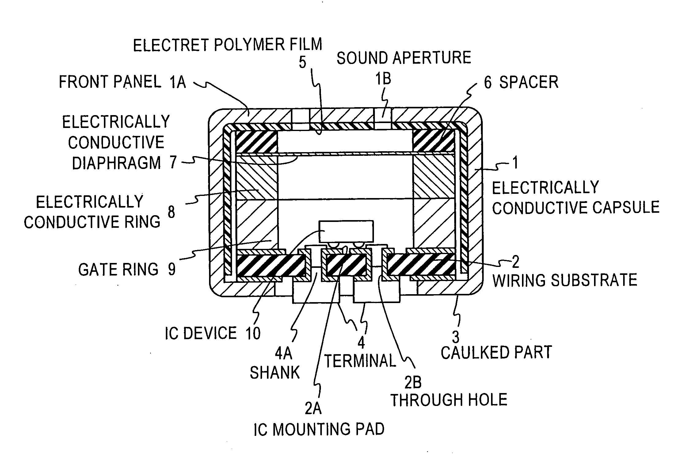
[0037] FIGS. 3 to 5 show an exemplary front-type electret condenser microphone to which the present invention has been applied. FIG. 3 is a cross-sectional view of the completed front-type electret condenser microphone, FIG. 4 is a perspective view of an exemplary structure of a terminal to be mounted to a wiring substrate 2, and FIGS. 5A and 5B are exploded perspective view of components of the front-type electret condenser shown in FIG. 3.

[0038] An electrically conductive capsule 1 is a cylinder having one end closed by a front panel 1A and the other end being open as shown in FIGS. 5A and 5B. While the capsule shown has a cylindrical shape, the shape of the capsule is not so limited. The front panel 1A has sound apertures 1B through which an acoustic wave is captured into the electrically conductive capsule 1. In the case of front-type electret condenser microphones, at least the inner surface of the front panel 1A of the electrically conductive capsule 1 is covered with an elec...

second embodiment

[0046]FIG. 6 shows an exemplary back-type or file-type electret condenser microphone to which the present invention has been applied. FIGS. 7A and 7B are exploded perspective views of components of the back-type or foil-type electret condenser microphone shown in FIG. 6. Provided in the back-type or foil-type electret condenser microphone are an electrically conductive diaphragm 7, an insulating spacer 6, and a fixed electrode 12 in this order from the front plate side of the electrically conductive capsule 1. Sound apertures 12A are formed in the fixed electrode 12 as well and the space between the fixed electrode 12 and a wiring substrate 2 is not sealed.

[0047] The back-type or foil-type electret condenser microphone has a cylindrical molded member 11 between the inner surface of the electrically conductive capsule 1 and the components. The cylindrical synthetic-resin molded member 11 insulates the fixed electrode 12 and a gate ring 9 from the electrically conductive capsule 1. T...

third embodiment

[0052]FIG. 9 shows a cross-sectional view of an exemplary reverse-type electret condenser microphone to which the present invention has been applied. FIG. 10A shows an exploded perspective view of components of the reverse-type electret condenser microphone shown in FIG. 9. Provided in the reverse-type electret condenser microphone are a fixed electrode 12, a spacer 6, and an electrically conductive diaphragm 7 in this order from the front panel side of the electrically conductive capsule 1. In the third embodiment, a metallic mesh 13 is provided between the fixed electrode 12 and the front panel 1A and the surface of the fixed electrode 12 that faces the electrically conductive diaphragm is covered with an electret polymer film 5 made of a heat-resistant material. The fixed electrode 12 and the electrically conductive diaphragm 7 are held at a given distance from each other by the thickness of the spacer 6. A cylindrical synthetic-resin molded member 11 attached to the inner periph...


PUM


Abstract

An object of the present invention is to provide a digital-output electret condenser microphone capable of being soldered on a wiring substrate of an apparatus by using a reflow furnace. An electret condenser microphone according to the present invention has an electret polymer film and a spacer that are formed of a heat-resistant material. Sound apertures are provided in a front panel of the electrically conductive capsule and/or the wiring substrate. Provided on the surface exposed in the open end of the electrically conductive capsule are multiple terminals, including at least a power supply terminal, a digital signal output terminal, and a clock input terminal. The terminals are protruded outward beyond a caulked part at the open end of the electrically conductive capsule.

Description

TECHNICAL FIELD [0001] The present invention relates to an electret condenser microphone used in apparatuses such as cellular phones, video cameras, and personal computers. BACKGROUND ART [0002] When an electronic component is to be mounted onto a wiring substrate, an automatic soldering apparatus called a reflow furnace is used to solder terminals of the component to pads provided on the wiring substrate. In the reflow furnace, the wiring substrate on which the component is disposed is passed over melted solder. While the wiring substrate is passing, a portion of the melted solder is brought into contact with the pads provided on the wiring substrate and the terminals of the component, thereby soldering the terminals of the component to the pads on the wiring substrate. Accordingly, the component is exposed to a high melting temperature (approximately 260° C.) of the solder for a brief moment. [0003] An electret condenser microphone converts an acoustic wave into an electric signal...

Claims


Application Information

Patent Timeline
IPC IPC(8): H04R25/00H04R17/02
CPCH04R19/016H04R1/04H04R31/006
Inventor IZUCHI, TOSHIRONAKANISHI, KENSUKEAWAMURA, RYUJI
Owner HOSIDEN CORP
Why Eureka
Try Eureka