Liquid zoom lens

Inactive Publication Date: 2007-05-10
SAMSUNG ELECTRO MECHANICS CO LTD
View PDF5 Cites 12 Cited by
  • Summary
  • Abstract
  • Description
  • Claims
  • Application Information

AI Technical Summary

Benefits of technology

[0026] An advantage of the present invention is that it provides a liquid zoom lens, which comprises a cylindrical body filled with electrolyte and insulating liquid therein to form a plurality of interfaces therebetween, each having a curvature changed by application of voltage to the electrolytes via electrodes connected with the electrolytes to embody both optical zoom function and auto-focus function at the same time by virtue of the variation in curvature of the interfaces.
[0027] Additional aspects and advantages of the present general inventive concept will be set forth in part in the description which follows and, in part, will be obvious from the description, or may be learned by practice of the general inventive concept.
[0028] According to an aspect of the invention, the above and other objects can be accomplished by the provision of a liquid zoom lens, comprising: a cylindrical body having a pair of glass lenses respectively coupled at upper and lower openings of the body; an auto-focus lens part including a first liquid insulating layer and a first electrolyte layer stacked at a lower portion of the body to form an interface therebetween; and an optical zoom lens part including a second liquid insulating layer and a second e

Problems solved by technology

For a lens system mounted to the mobile terminal and used to pick up the image of the object, it generally suffers from various kinds of aberration, such as spherical aberration, astigmatism, distortion aberration, etc. causing deformation of the shape or the morphology of the image of the object due to influence of incident light having various wavelengths, which is incident on the lens upon image pickup of the object.
As such, the digital zoom is advantageous in terms of miniaturization and compactness, but has a problem in that clear resolution cannot be achieved upon image pickup by the zoom operation.
Hence, the optical zoom is disadvantageous in that it requires a large space for a lens part and a lens barrel surrounding the lens part.
Nevertheless, a recent tendency of miniaturization and compactness in the market requires a decrease in space for changing the focal distance, and thus, manufacturers have mainly released mobile terminals which incorporate the digital zoom function therein rather than the optical zoom function.
Consequently, t

Method used


Image

  • Liquid zoom lens
  • Liquid zoom lens
  • Liquid zoom lens

Examples


Example

[0039] Reference will now be made in detail to the embodiments of the present general inventive concept, examples of which are illustrated in the accompanying drawings, wherein like reference numerals refer to the like elements throughout. The embodiments are described below in order to explain the present general inventive concept by referring to the figures.

[0040] Hereinafter, preferred embodiments of the present invention will be described in detail with reference to the accompanying drawings.

[0041] Structure of Liquid Zoom Lens

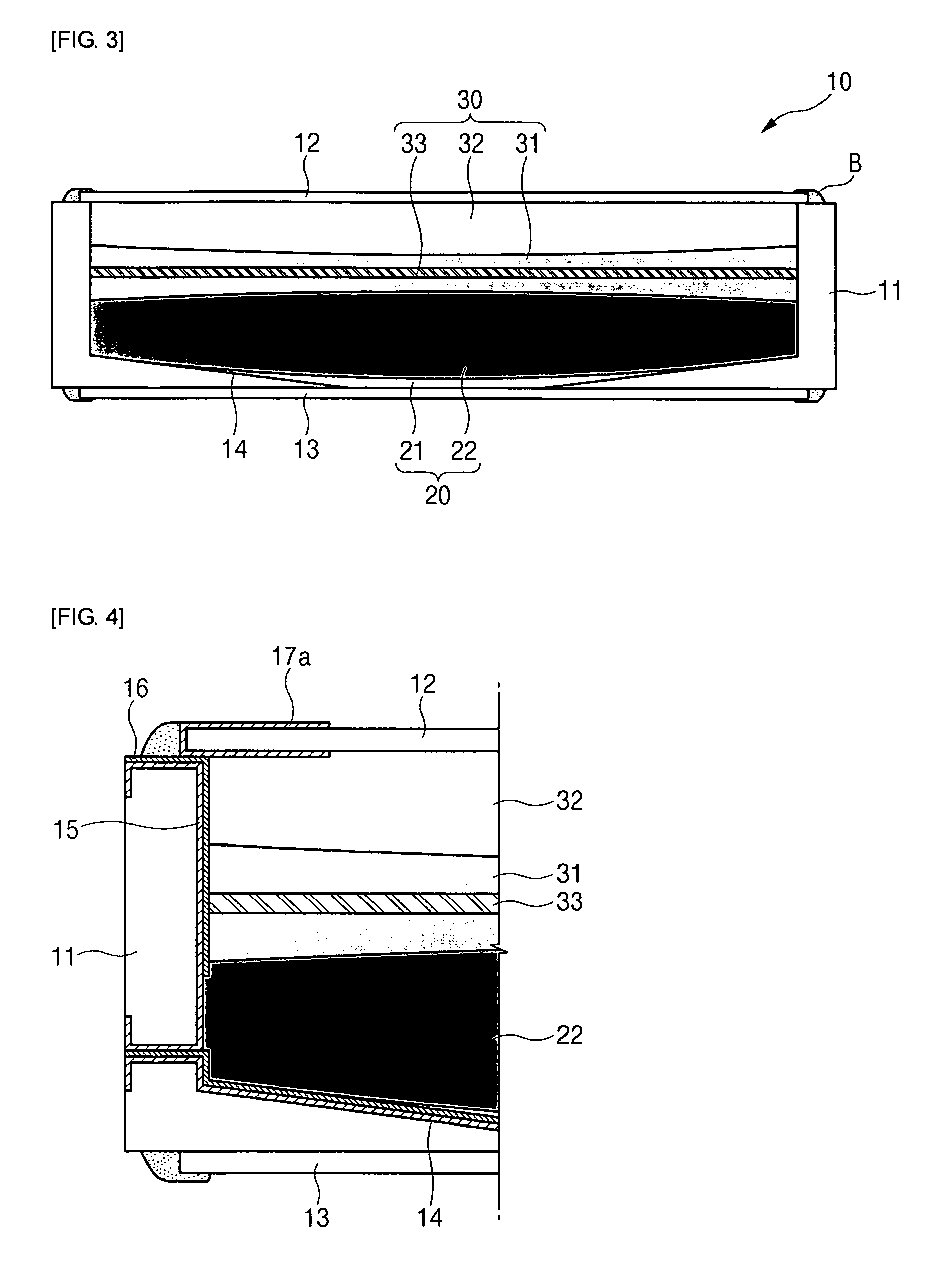
[0042]FIG. 3 is a cross-sectional view of a liquid zoom lens according to the present invention, and FIG. 4 is an enlarged cross-sectional view of one side of a body of the liquid zoom lens according to the present invention. Referring to FIGS. 3 and 4, a liquid zoom lens 10 according to the present invention comprises a cylindrical body 11, which has glass lenses 12 and 13 (also referred to as “upper” and “lower” glasses) respectively bonded to upper a...


PUM


Abstract

Disclosed herein is a liquid zoom lens. The liquid zoom lens comprises a cylindrical body including glass lenses respectively coupled at upper and lower openings to the body, an auto-focus lens part including a first liquid insulating layer and a first electrolyte layer stacked at a lower portion of the body to form an interface therebetween, and an optical zoom lens part including a second liquid insulating layer and a second electrolyte layer stacked on the first electrolyte layer to form an interface therebetween and a lens positioned in the second liquid insulating layer and fixed to the body with an outer peripheral surface of the lens closely contacting an inner peripheral surface of the body. The liquid zoom lens enables an auto-focus function and an optical zoom function to be performed simultaneously by means of a single liquid lens having a variable curvature.

Description

CROSS-REFERENCE TO RELATED APPLICATIONS [0001] The application claims the benefit of Korea Patent Application No. 10-2005-0103780 filed with the Korea Intellectual Property Office on Nov. 1, 2005, the disclosure of which is incorporated herein by reference. BACKGROUND OF THE INVENTION [0002] 1. Field of the Invention [0003] The present invention relates to a liquid zoom lens. More particularly, the present invention relates to a liquid zoom lens, which includes a cylindrical body filled with electrolyte and insulating liquid therein to form a plurality of interfaces, each having a curvature changed by application of voltage, and a disk-shaped lens positioned in the electrolyte provided at an upper side to embody both optical zoom function and auto-focus function by variation in curvature of the interfaces resulting from the application of voltage to the interface of the electrolyte via electrodes formed of metal coating layers on the body. [0004] 2. Description of the Related Art [0...

Claims


Application Information

Patent Timeline
IPC IPC(8): G03B17/00G02B3/14G02B7/02G02B7/08G02B15/10G02B15/15
CPCG02B3/14G02B13/0025G02B13/003G02B13/0035G02B13/006G02B13/0075G02B13/009G02B26/005G03B13/36G02B3/12
Inventor LEE, YOUNG HOBAE, JAE YOUNGKIM, SUNG CHANYANG, JIN HYUCKJUNG, HA YONG
Owner SAMSUNG ELECTRO MECHANICS CO LTD
Why Eureka
Try Eureka