Fuel reformer

a technology of fuel reformer and fuel cell, which is applied in the direction of sustainable manufacturing/processing, physical/chemical process catalyst, final product manufacturing, etc., can solve the problems of large thermal stress, high manufacturing cost, and considerable structure complexity, and achieves easy bending, large surface area, and no thermal stress.

Active Publication Date: 2007-05-10
EBARA CORP
View PDF9 Cites 21 Cited by
  • Summary
  • Abstract
  • Description
  • Claims
  • Application Information

AI Technical Summary

Benefits of technology

[0018] In the fuel reformer of the present invention for achieving the second and third object, where the connection flow pipe 19 has an expandable member expandable and contractible in the axial direction of the connection flow pipe 19, the distortion caused by thermal expansion of the high-temperature unit 2, the medium-low-temperature unit 3 and the vessel 13 when these are shifted from a cooled state at start-up to a heated state during steady operation can be absorbed by expansion or contraction of the connection flow pipe 19. Thus, even if the start-up and operation of the fuel reformer are repeated, the influence of thermal stress is not increased. The member to expand or contract may be a member having a wavy cross-section like a bellows or a member which can be easily bent like a diaphragm. In addition, such an expandable member has a larger surface area than a straight pipe, the heat exchange between the reformate flowing through it and the reforming additive water flowing outside it can be performed efficiently.
[0019] In the fuel reformer of the present invention, where the high-temperature unit 2 is located on the upper side and the medium-low-temperature unit 3 is located below the high-temperature unit 2, the phase change from water to steam can occur naturally when a reforming additive water passage is provided since the difference in specific gravity between water and steam coinc...

Problems solved by technology

Thus, the conventional multiple-cylinder type reformers have a problem that the structure is considerably complicated and a high manufacturing cost is required.
Also in conventional multiple-cylinder type reformers, since the cylindrical partitions for dividing the sections have large lengths and areas and since the differences in temperature between the sections are large, a large thermal ...

Method used


Image

  • Fuel reformer
  • Fuel reformer
  • Fuel reformer

Examples


first embodiment

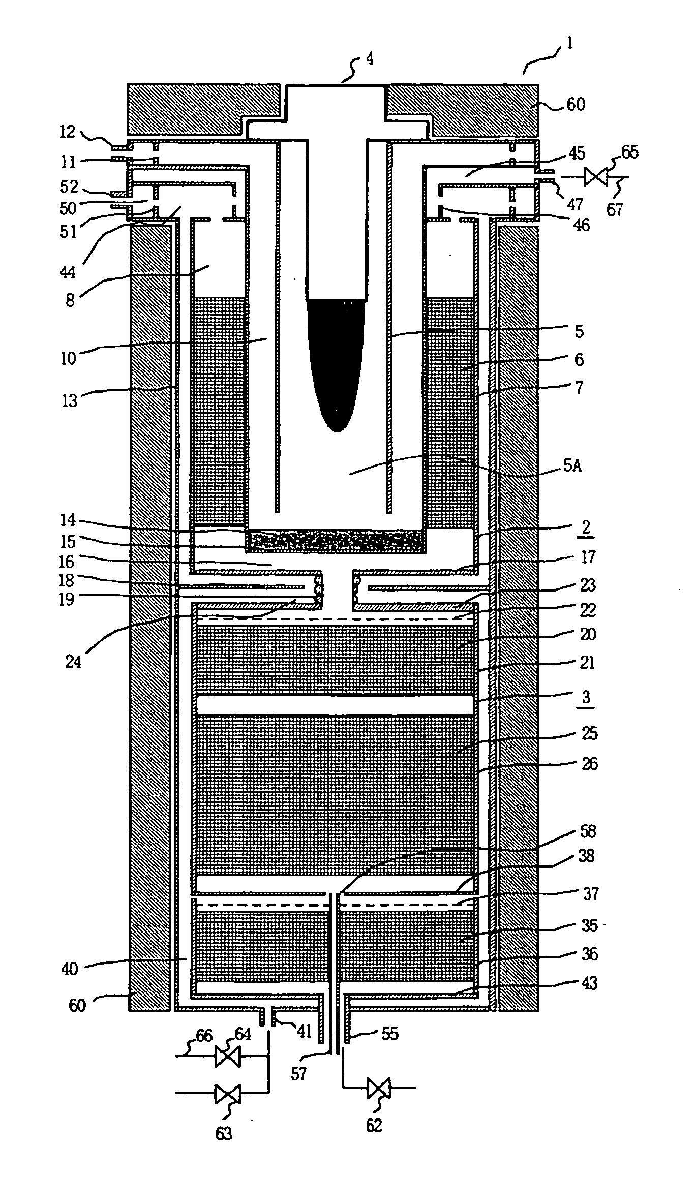
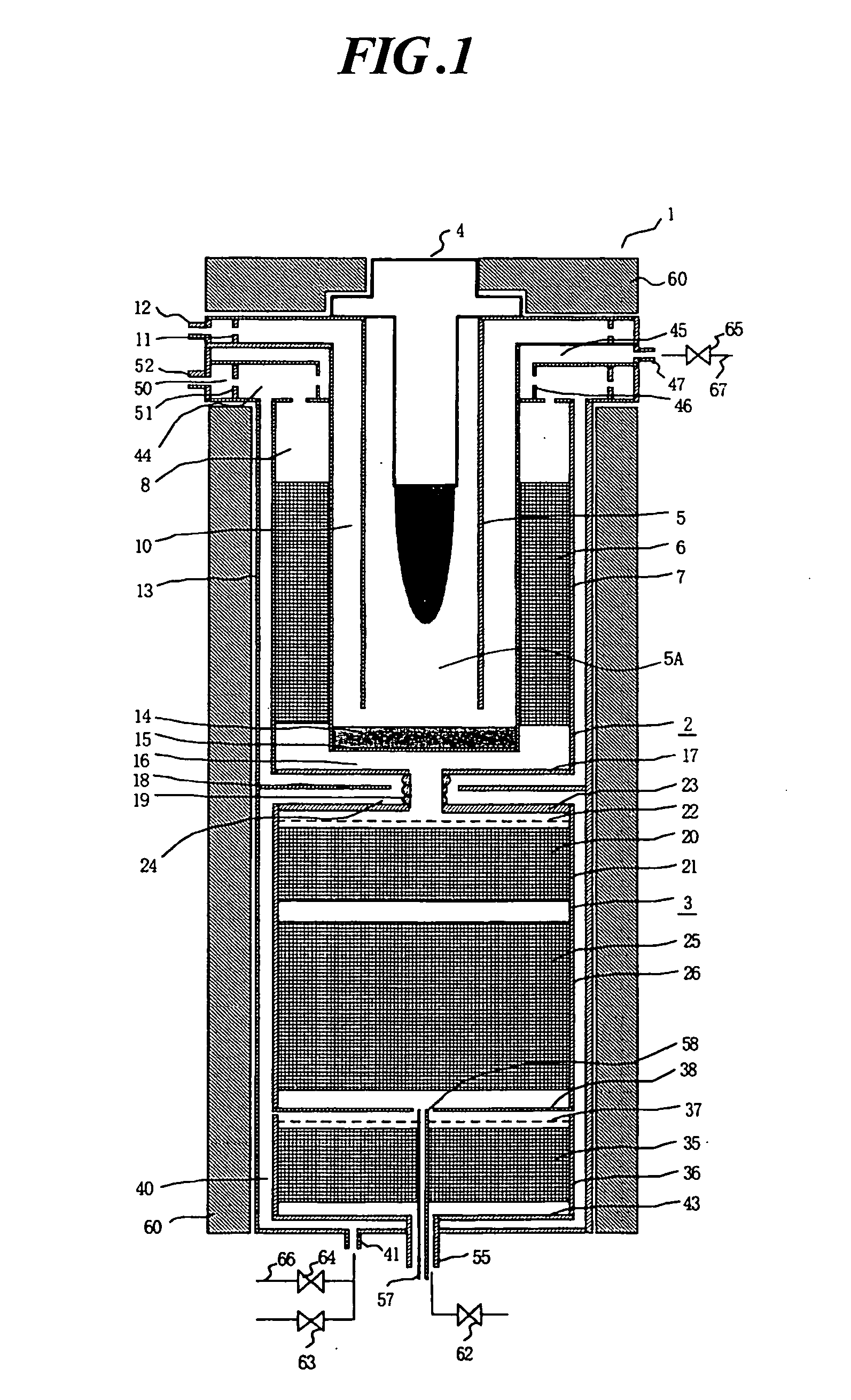
[0046]FIG. 1 is a vertical cross-sectional view illustrating a fuel reformer according to the present invention. As shown in the drawing, a reformer 1 has a reformer upper section 2 as a high-temperature unit and a reformer lower section 3 as a medium-low-temperature unit. The reformer upper section 2 has a burner 4 for burning fuel, a combustion cylinder 5 disposed coaxially with the burner 4, and a reforming section 7 having an annular body and housing a reforming catalyst-filled layer 6. The burner 4 is located generally on the central axis of the combustion cylinder 5. As the reforming catalyst for use in the reforming catalyst-filled layer 6, any substance can be use as long as it can accelerate a reforming reaction. For example, a Ni-based reforming catalyst or a Ru-based reforming catalyst can be used. The reforming catalyst may be in the form of particles or have a cylindrical, honeycomb or monolithic shape. A detailed illustration of the burner 4 is not given here.

[0047] A ...

second embodiment

[0076]FIG. 6 is a constitutional block diagram illustrating the present invention. In the second embodiment, a first reforming additive water flow rate control section 70 and a second reforming additive water flow rate control section 72 are provided so that the operation of the fuel reformer shown in FIG. 1 under steady conditions can be improved. The first reforming additive water flow rate control section 70 has thermometers T1 to T5 such as thermocouples for measuring the temperatures of different parts of the reformer upper section 2 and the reformer lower section 3 as input instruments, and a first flow meter F1 for measuring the flow rate of the first reforming additive water flowing through the first reforming additive water passage 40, and transmits a valve opening signal to the flow control valve 64. In the reformer upper section 2, a first thermometer T1 for measuring the temperature of the first reforming additive water in the vicinity of the mixing chamber 44 and a seco...


PUM

PropertyMeasurementUnit
Currentaaaaaaaaaa
Temperatureaaaaaaaaaa
Vacuumaaaaaaaaaa

Abstract

A fuel reformer which is relatively simple in structure and can be manufactured at a low cost is provided. A fuel reformer includes: a high-temperature unit 2 having a combustion chamber 5A in which fuel is burned, and a reforming section 7 disposed on the outer peripheral surface side of the combustion chamber 5A and filled with a reforming catalyst in an annular shape; a medium-low-temperature unit 3 having a shift converter section (21, 26) located on the side where the medium-low-temperature unit 3 is connected to the high-temperature unit 2 and filled with a shift converter catalyst in a cylindrical shape, and a selective oxidation section 36 located on the side opposite the side where the medium-low-temperature unit 3 is connected to the high-temperature unit 2 and filled with a selective oxidation catalyst in a cylindrical shape; a connection flow pipe 19 for supplying reformate having passed through the reforming section of the high-temperature unit 2 to the shift converter section side in the medium-low-temperature unit 3; and a vessel 13 for integrally housing the high-temperature unit 2 and the medium-low-temperature unit 3 connected by the connection flow pipe 19.

Description

TECHNICAL FIELD [0001] The present invention relates to a fuel reformer for reforming a hydrocarbon-based fuel to produce hydrogen-rich reformate and, more particularly, to an integrated fuel reformer which is relatively simple in structure and can be manufactured at a low cost. The present invention also relates to an integrated fuel reformer which can process various types of hydrocarbon fuels including gas fuels such as a city gas, LPG and anaerobic digestion gas and liquid fuels such as kerosene and gasoline to produce reformate suitable for a solid macromolecule fuel cell. BACKGROUND ART [0002] In recent years, fuel cell cogeneration systems which can supply both heat and electricity are being developed from the viewpoint of preservation of the global environment. In such a system, a hydrocarbon fuel such as natural gas is reformed with steam to produce hydrogen-rich reformate (reformed gas) in a reforming device, and the produced reformate is supplied to a fuel cell to generat...

Claims


Application Information

Patent Timeline
IPC IPC(8): B01J10/00B01J19/00B01J8/04B01J19/24C01B3/38C01B3/48H01M8/04H01M8/06
CPCB01J8/0453B01J8/0469B01J8/0492B01J8/0496B01J19/2485B01J2208/00221B01J2208/00486B01J2208/00495B01J2208/00504B01J2208/0053B01J2208/00716B01J2208/025B01J2219/00006C01B3/384C01B3/48C01B2203/0233C01B2203/0288C01B2203/044C01B2203/047C01B2203/066C01B2203/0816C01B2203/0844C01B2203/1241C01B2203/1247C01B2203/1276C01B2203/1294C01B2203/1619C01B2203/169C01B2203/82H01M8/04022H01M8/0618H01M8/0631H01M8/0668Y02E60/50Y02P70/50
Inventor SU, QINGQUAN
Owner EBARA CORP
Why Eureka
Try Eureka