
Intraocular shunt device and method

Inactive Publication Date: 2007-05-10
BAUSCH & LOMB INC
View PDF65 Cites 85 Cited by
  • Summary
  • Abstract
  • Description
  • Claims
  • Application Information

AI Technical Summary

Benefits of technology

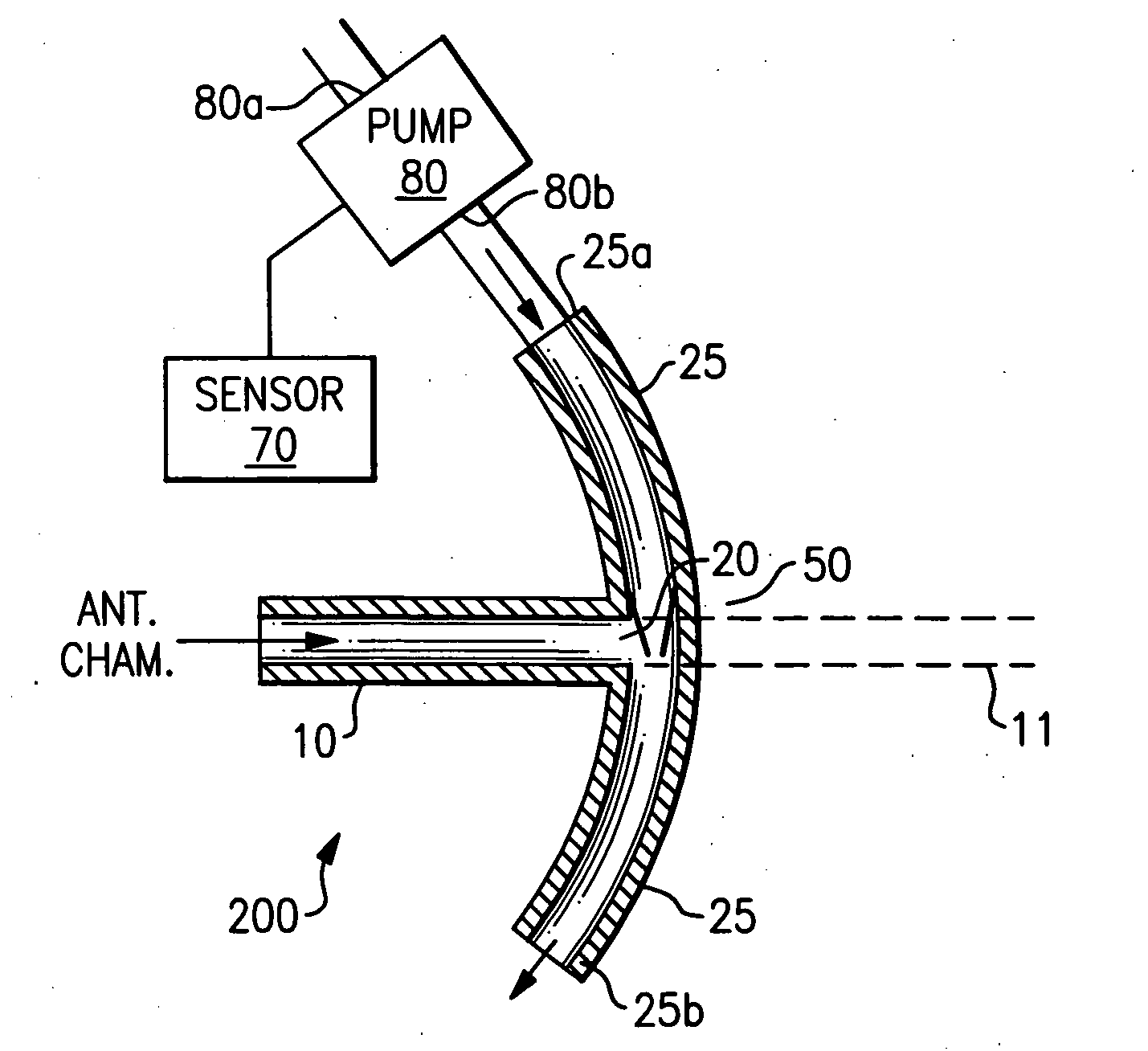
[0012] Aspects of the present invention are directed to a shunt device providing improved flow control. In one embodiment the shunt comprises a conduit sized to fit within Schlemm's canal, the conduit having a proximal end, a distal end, and an inlet intermediate the proximal end and the distal end; and a Venturi feature configured and arranged within the conduit so as to be capable of controlling flow from the inlet into the conduit. The shu

Problems solved by technology

Glaucoma is a pathological condition of the eye often resulting in elevated intraocular pressure.
If the intraocular pressure remains elevated for a long enough period of time, total vision loss occurs.
Because glaucoma is a major cause of blindness, glaucoma is a significant public health problem.
High pressure develops in an eye as a result of glaucoma because of an intraocular fluid imbalance.
In glaucoma, the resistance through the canalicular outflow system is abnormally high, thus causing internal fluid imbalance.
It is believed that an abnormal metabolism of the trabecular cells leads to an excessive build up of extracellular materials or a build up of abnormally “stiff” materials in this area.
With the increased resistance, the aqueous fluid builds up in the anterior chamber because it cannot exit fast enough to maintain the intraocular fluid balance.
The increased IOP compresses the axons in the optic nerve (which carries visual information from the eye to the brain) and also may compromise the vascular supply to the optic nerve.
The medication has many serious side effects including: heart failure, respiratory distress, hypertension and depression.
The trabeculectomy is associated with many problems, including scarring and infection that results from bacteria entering the eye through the hole in the sclera.
Most of the problems that have developed with such shunt devices and procedures have occurred because aqueous fluid is drained from inside of the eye to the surface of the eye.
However, such devices have not provided suitable flow control.

Method used


Image

  • Intraocular shunt device and method
  • Intraocular shunt device and method
  • Intraocular shunt device and method

Examples


Embodiment Construction

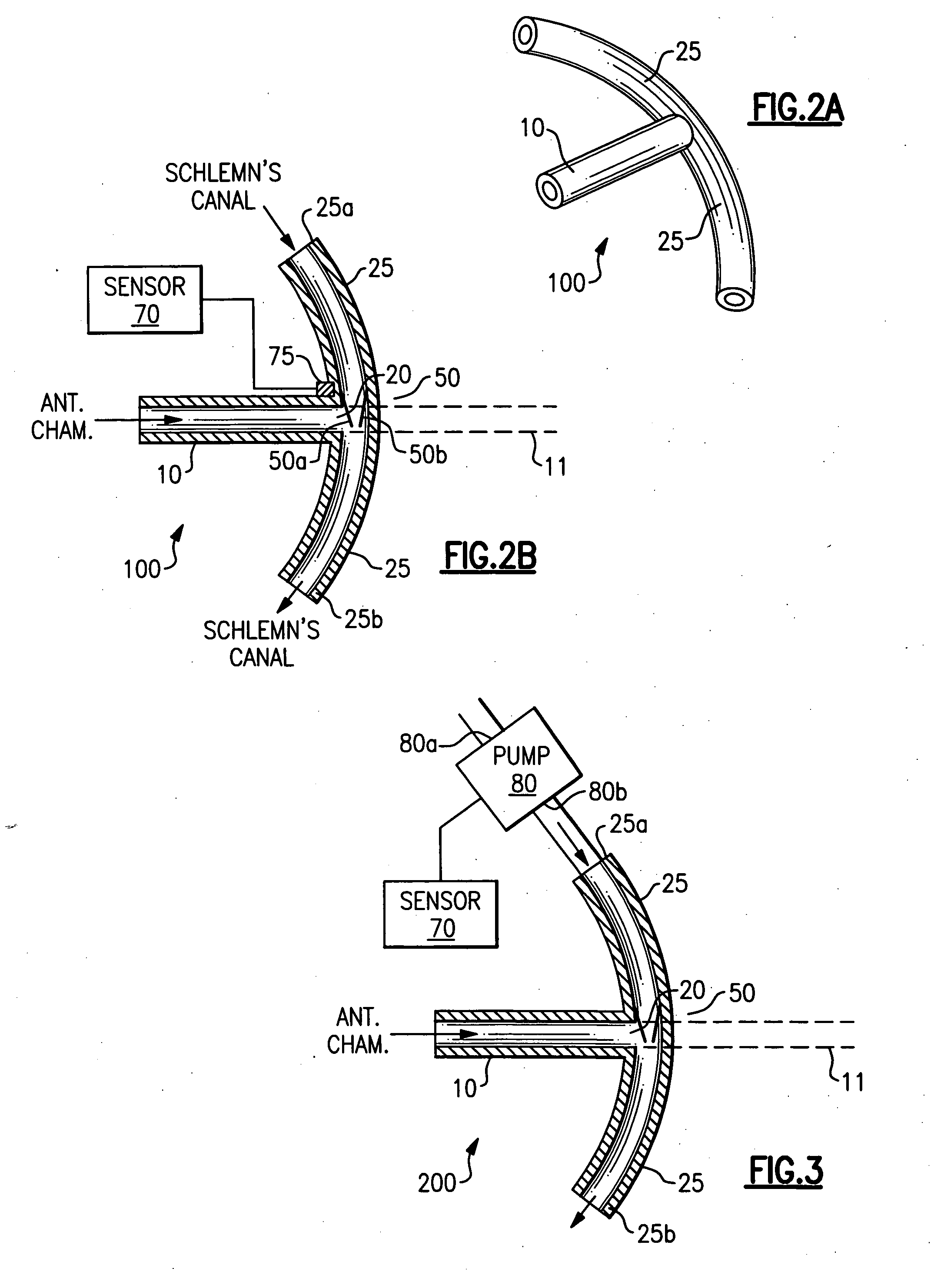
[0024] Aspects of the present invention are directed to a shunt, comprising: a conduit sized to fit within Schlemm's canal, the conduit having a proximal end, a distal end, and an inlet intermediate the proximal end and the distal end; and a Venturi feature configured and arranged within the conduit so as to be capable of controlling flow from the inlet into the conduit.

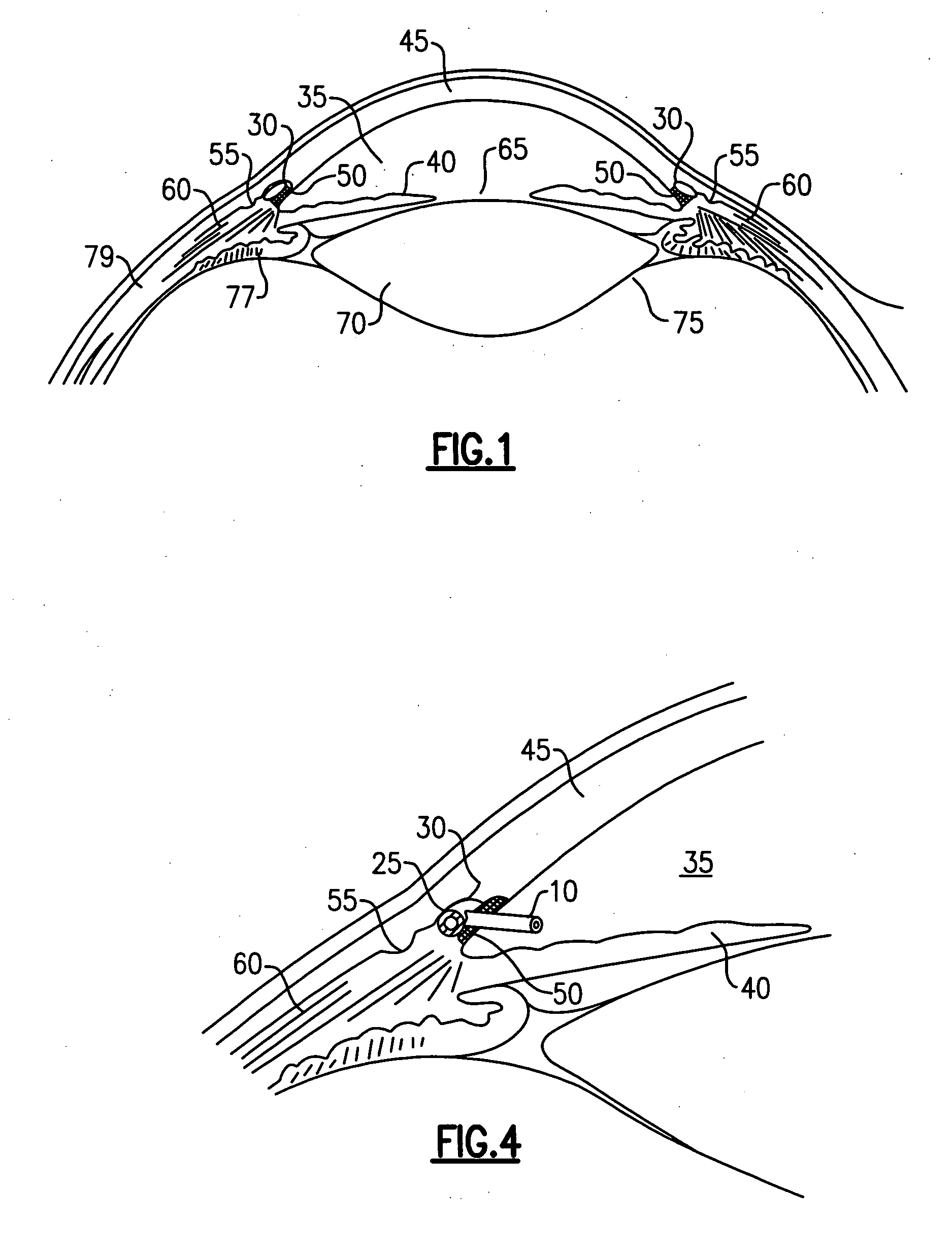
[0025]FIG. 2A is a schematic, perspective view of an embodiment of a shunt 100 according to aspects of the present invention including a Venturi feature (not shown). Shunt 100 is comprised of two portions, a conduit 25 and an inlet 10. FIG. 2B is a cross sectional view of shunt device 100 illustrating the internal fluid communication path. FIG. 2B also illustrates Venturi feature 50 disposed in the shunt to control fluid flow from the anterior chamber of an eye into Schlemm's canal. During operation of the device, conduit 25 is disposed in a portion of Schlemm's canal, and inlet 10 is exposed to the anterior chamber...


PUM


Abstract

A shunt having a conduit sized to fit within Schlemm's canal, the conduit having an inlet intermediate a proximal end and a distal end and a Venturi feature arranged within the conduit so as to control flow from the inlet into the conduit. The shunt may include a pressure sensor capable of measuring pressure within an eye, coupled to the Venturi feature, the Venturi feature being configured to control flow from the inlet into the conduit in response to a pressure measurement from the sensor. Also, the pressure sensor may be coupled to a pump that is adapted to control flow from the inlet into the conduit in response to a pressure measurement from the sensor.

Description

FIELD OF INVENTION [0001] The present invention relates to intraocular treatment devices and methods, and more particularly to controllable shunts and methods for controlling intraocular pressure. BACKGROUND OF THE INVENTION [0002] Glaucoma is a pathological condition of the eye often resulting in elevated intraocular pressure. If the intraocular pressure remains elevated for a long enough period of time, total vision loss occurs. The blindness that results from glaucoma involves both central and peripheral vision and has a major impact on an individual's ability to lead an independent life. Because glaucoma is a major cause of blindness, glaucoma is a significant public health problem. [0003] The following explanation of glaucoma is given with reference to the schematic illustration of the eye in FIG. 1. High pressure develops in an eye as a result of glaucoma because of an intraocular fluid imbalance. The pertinent fluid, known as aqueous humor, is formed in the posterior chamber ...

Claims


Application Information

Patent Timeline
IPC IPC(8): A61M5/00
CPCA61B3/16A61F9/00781
Inventor LEVY, BRIAN
Owner BAUSCH & LOMB INC
Learn More