Assembling an annular combustion chamber of a turbomachine
- Summary
- Abstract
- Description
- Claims
- Application Information
AI Technical Summary
Benefits of technology
Problems solved by technology
Method used
Image
Examples
Embodiment Construction
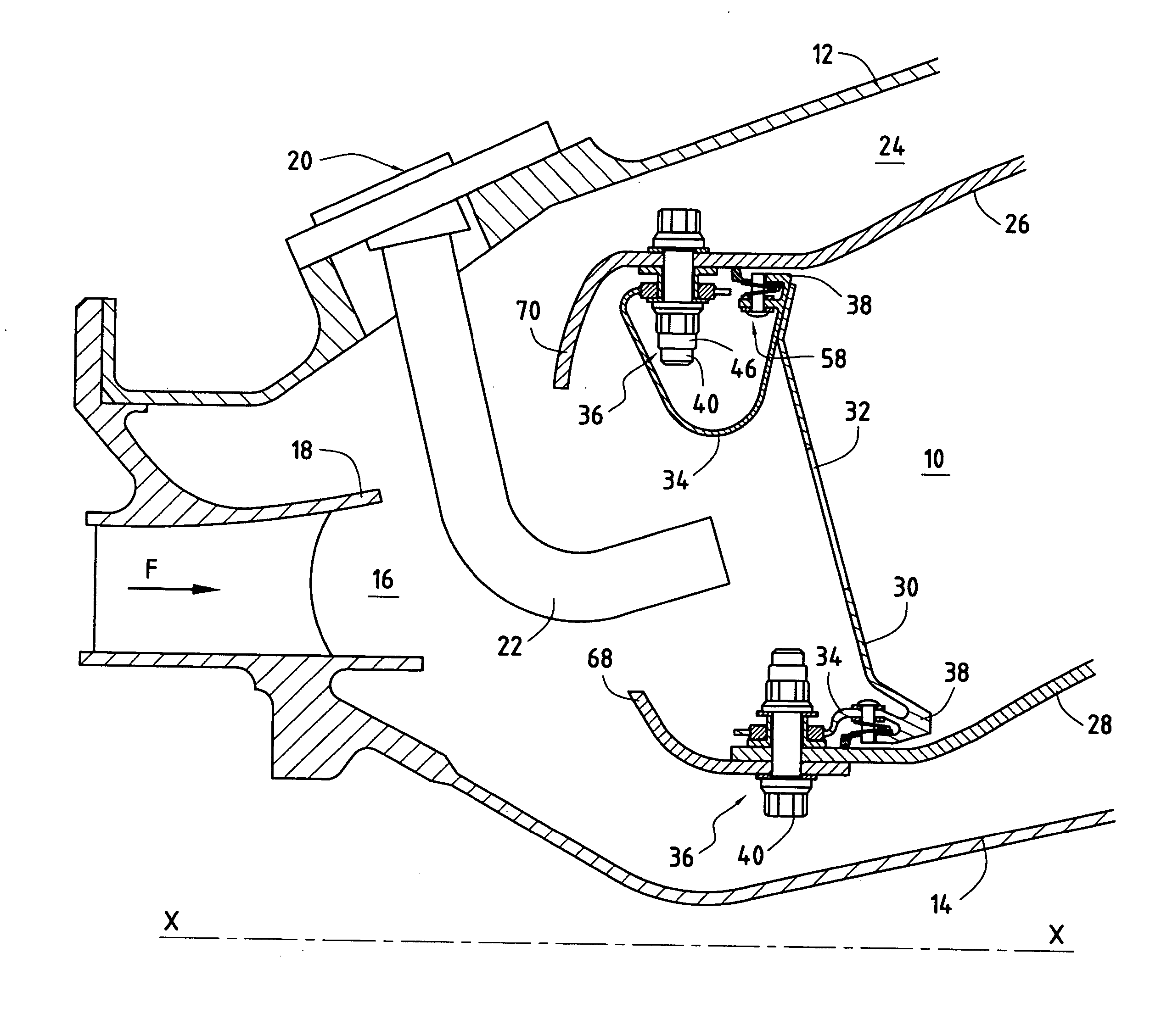
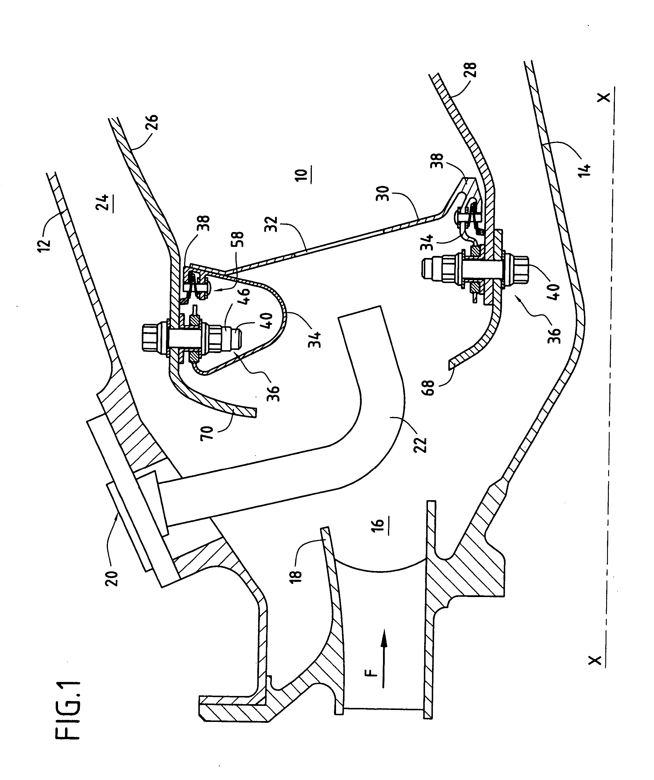
[0022]FIG. 1 is a fragmentary axial section view of a turbomachine combustion chamber 10 in its environment.
[0023] An outer annular shroud (or outer casing) 12 and an inner annular shroud (or inner casing) 14 coaxial therewith are centered on the axis X-X of the turbomachine. An annular space 16 formed between these two shrouds receives compressed air in a general stream F coming from a compressor (not shown) of the turbomachine via an annular diffusion duct 18. This air is for combustion of the fuel in the chamber 10.
[0024] A plurality of injection systems 20 are distributed regularly around the diffusion duct 18 and open out into the annular space 16. Each of these injection systems is provided with a fuel injection nozzle 22 secured to the outer shroud 12. In order to simplify the drawings, the mixer and the deflector associated with each injection nozzle are omitted.
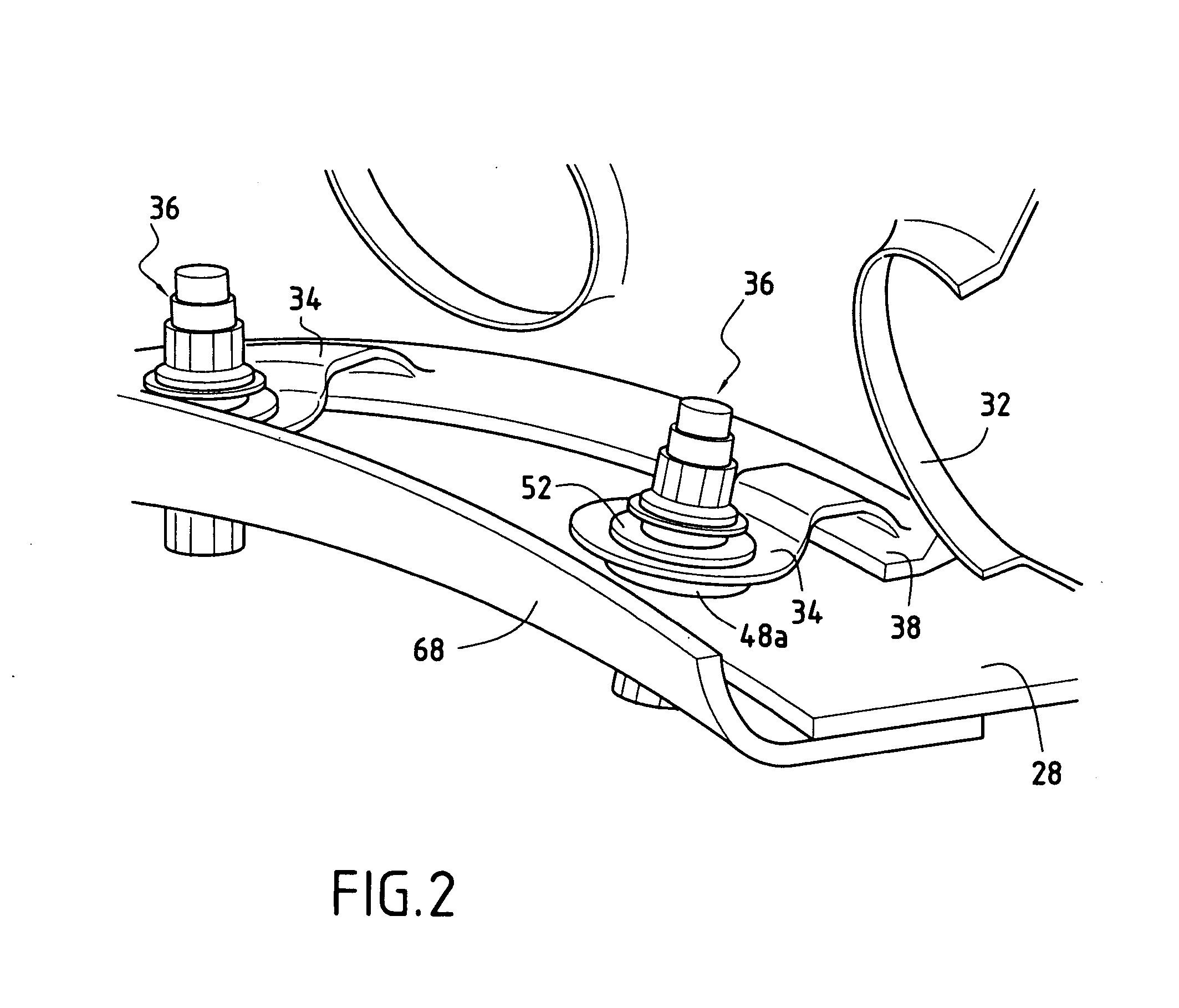
[0025] The combustion chamber 10 of the turbomachine is mounted inside the annular space 16 so as to leave resp...
PUM
 Abstract
Description
Claims
Application Information
 - R&D
- Intellectual Property
- Life Sciences
- Materials
- Tech Scout
- Unparalleled Data Quality
- Higher Quality Content
- 60% Fewer Hallucinations
Browse by: Latest US Patents, China's latest patents, Technical Efficacy Thesaurus, Application Domain, Technology Topic, Popular Technical Reports.
© 2025 PatSnap. All rights reserved.Legal|Privacy policy|Modern Slavery Act Transparency Statement|Sitemap|About US| Contact US: help@patsnap.com


