
Permanent-magnet generator

a permanent magnet generator and generator technology, applied in the direction of mechanical energy handling, magnetic circuit rotating parts, shape/form/construction, etc., can solve the problems of hysteresis loss and eddy current loss, certain the rotation variance of the generator itself adversely affects the shaft side, so as to reduce the quantity of rotation imbalance, reduce the quantity of balance correction processing, and improve the effect of rotation imbalan

Active Publication Date: 2007-05-17
MITSUBISHI ELECTRIC CORP
View PDF7 Cites 10 Cited by
  • Summary
  • Abstract
  • Description
  • Claims
  • Application Information

AI Technical Summary

Benefits of technology

[0013] In view of the foregoing status of the art, it is an object of this invention to provide a permanent-magnet generator that has a bowl-shaped fly wheel integrally formed with a boss part by casting or hot forging, and that enables improvement in the quantity of rotation imbalance and significant reduction in the quantity of balance correction processing (drilling), which is necessary in a later process.
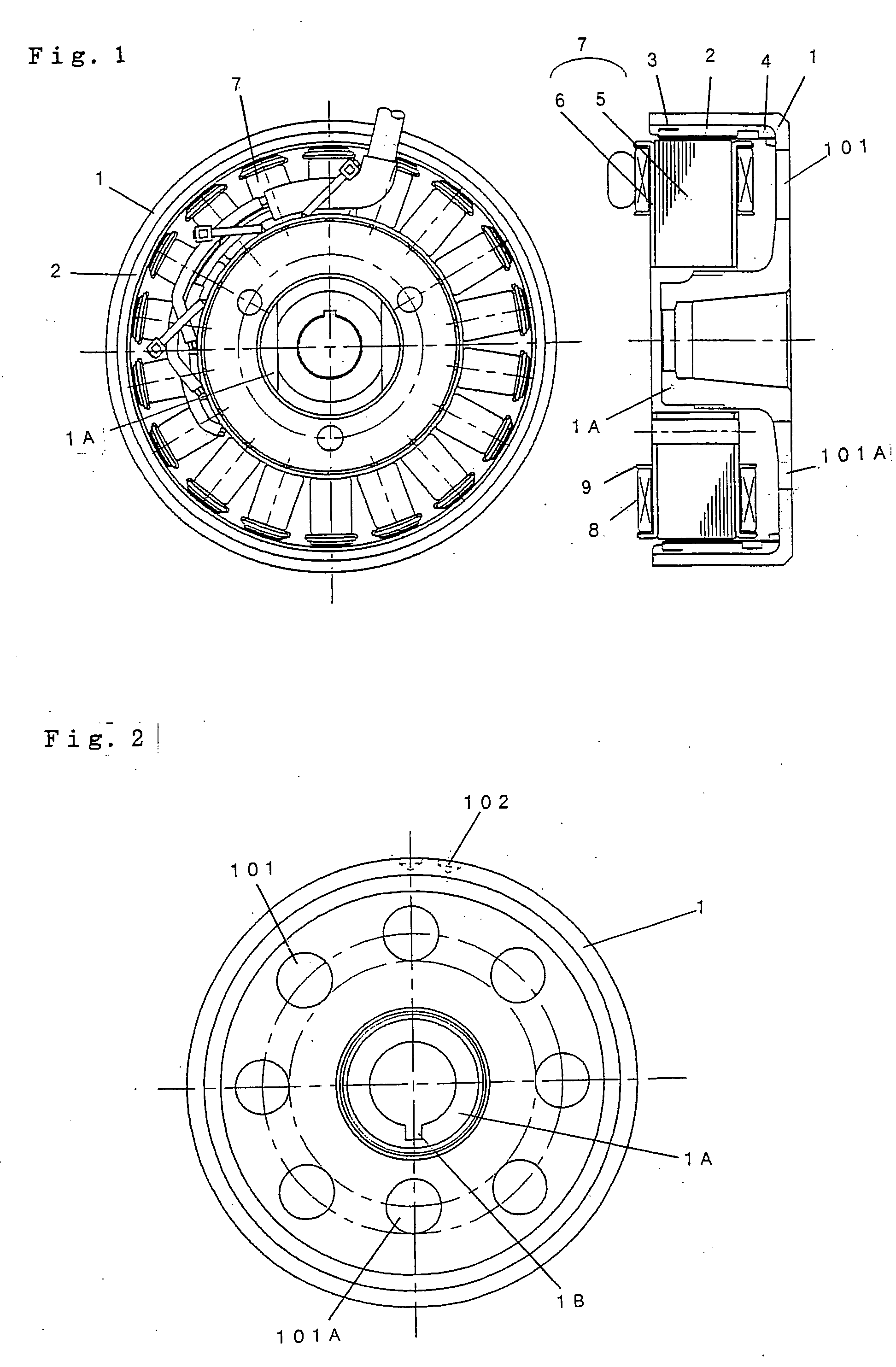
[0014] According to this invention, a permanent-magnet generator includes: a bowl-shaped fly wheel produced by casting or hot forging, having a circumferential wall part and a bottom wall part, and having a boss part for supporting a rotating shaft, the boss part being integrally formed at the center of the bottom wall part; plural magnets provided on an inner circumferential surface of the circumferential wall part of the fly wheel; and a generating coil wound on a laminated core arranged to face the magnets. Plural vents are arranged with spacing from each other substantially circularly in the bottom wall part of the fly wheel, and a key groove to be coupled with the rotating shaft is provided at a part of the boss part. Arrangement of at least one of the plural vents is made unequal in order to reduce the quantity of rotation imbalance including that of the key groove.
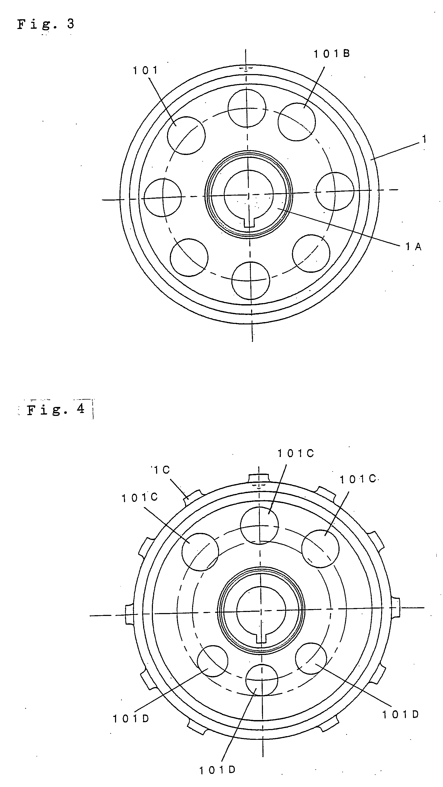
[0015] According to this invention, in the permanent-magnet generator having the fly wheel and the boss part integrally produced by casting or hot forging, the arrangement of at least one of the plural vents arranged in the bottom wall part of the fly wheel is made unequal. Thus, the quantity of rotation imbalance including that of the key groove formed in the boss part can be reduced and the quantity of balance correction processing (drilling), which is necessary in a later process, can be reduced.

Problems solved by technology

However, when the rotor rotates, an alternating field generated by the magnet causes hysteresis loss and eddy-current loss in a laminated core of a stator.
Also, the fly-wheel permanent-magnet generator is often directly connected with a shaft of an internal combustion engine or the like, and the rotation variance from the shaft and the rotation variance of the generator itself adversely affect the shaft side.
Since processing variance, variation of attached components (plural magnets are installed with a gap from each other) and the like cause a certain quantity of rotation imbalance, balance correction processing such as drilling needs to be performed many times in a later process.
However, if the fly wheel is produced by casting or hot forging, rotation imbalance is caused by variance in density (specific gravity) rather than dimensional variance.
Therefore, it is difficult to reduce the quantity of rotation imbalance to the required level, simply by adjusting the size (area) of one or some of the vents as described above.
Moreover, even if the processing variance and the variation of attached components are addressed to improve the accuracy, it is difficult to completely eliminate the rotation imbalance, because of the influence of a key groove provided at the center of the boss part.

Method used


Image

  • Permanent-magnet generator
  • Permanent-magnet generator
  • Permanent-magnet generator

Examples


embodiment 1

[0025] Embodiment 1 of this invention will now be described with reference to FIGS. 1 to 4.

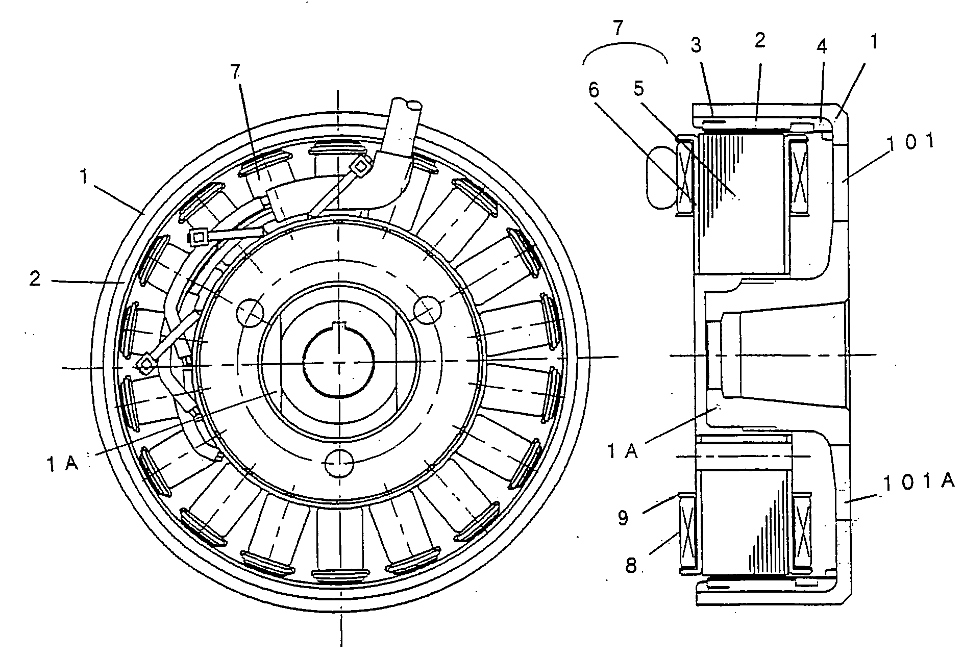
[0026]FIG. 1 is a plan view and longitudinal sectional view showing a permanent-magnet generator according to Embodiment 1. Numeral 1 represents a bowl-shaped fly wheel having a circumferential wall part and a bottom wall part. The fly wheel is produced by casting or hot forging. A boss part 1A having a key groove 1B formed therein is integrally formed at the center of the bottom wall part. The key groove 1B functions for connection with and rotation stop of a rotating shaft of an internal combustion engine or the like. The key groove 1B is processed at the center of the boss part 1A.

[0027] Numeral 2 represents plural magnets provided in the circumferential direction on the circumferential wall part of the fly wheel 1. Numeral 3 represents a cylindrical production ring adhering to and fitted with the inner side of the. circularly provided magnets 2. Numeral 4 represents a resin or mold mater...

embodiment 2

[0039] FIGS. 6 to 9 show a case of applying a fly wheel with a reduced thickness for reduction in size and weight, as Embodiment 2. Instead of vents, plural recessed parts 201 are arranged substantially circularly with spacing from each other on the inner surface of the bottom wall part of the fly wheel 1, and the shape or arrangement spacing (pitch) of at least one of the plural recessed parts 201 is made unequal in order to reduce the quantity of rotation imbalance including that of the key groove 1B.

[0040]FIG. 6 shows an example in which the shape of a recessed part 201A facing the key groove 1B, which is one of the recessed parts. FIG. 7 shows an example in which the arrangement spacing (pitch) of a recessed part 201B, which is one of the recessed parts, is changed. FIG. 8 shows an example in which the area of a recessed part 201C, which is one of the recessed parts, is increased. FIG. 9 shows an example in which an inclined surface 1F is formed at the bottom of a recessed part...


PUM


Abstract

A permanent-magnet generator is provided that has a bowl-shaped fly wheel integrally formed with a boss part by casting or hot forging, and that enables improvement in the quantity of rotation imbalance and significant reduction in the quantity of balance correction processing (drilling), which is necessary in a later process. The permanent-magnet generator has a bowl-shaped fly wheel produced by casting or hot forging, having a circumferential wall part and a bottom wall part, and having a boss part for supporting a rotating shaft, the boss part being integrally formed at the center of the bottom wall part. The plural vents are arranged substantially circularly with spacing from each other in the bottom wall part of the fly wheel, and a key groove for coupling with the rotating shaft is provided at a part of the boss part. The arrangement of at least one of the plural vents is made unequal in order to reduce the quantity of rotation imbalance including that of the key groove.

Description

BACKGROUND OF THE INVENTION [0001] 1. Field of the Invention [0002] This invention relates to a fly-wheel permanent-magnet generator. [0003] 2. Description of the Related Art [0004] In a conventional fly-wheel permanent-magnet generator, a bowl-shaped fly wheel having a magnet on the inner surface of its circumferential wall is used as a rotor. However, when the rotor rotates, an alternating field generated by the magnet causes hysteresis loss and eddy-current loss in a laminated core of a stator. The magnetic force and the quantity of imbalance of the rotor itself cause variance in the rotation locus. The rotation variance leads to variance in the rotation accuracy (quantity of air gap between the stator and the rotor) and largely affects the power generation characteristic (output characteristic). [0005] Also, the fly-wheel permanent-magnet generator is often directly connected with a shaft of an internal combustion engine or the like, and the rotation variance from the shaft and ...

Claims


Application Information

Patent Timeline
IPC IPC(8): H02K9/00H02K1/32H02K7/00
CPCH02K1/2786H02K7/04H02K9/06H02K15/165H02K1/2791
Inventor HASHIBA, MITSUHARUKIHARA, NOBUHIRO
Owner MITSUBISHI ELECTRIC CORP
Learn More