Method for controlling overcoat recession in a magnetic thin film head

a thin film head and overcoat technology, applied in the direction of maintaining the head carrier alignment, manufacturing tools, instruments, etc., can solve the problems of generating a relatively significant amount of heat, physical contact, damage to the disk surface, etc., and achieves a slight degree of abrasion and softening the surface of the slider material

Inactive Publication Date: 2007-05-17
SAE MAGNETICS (HK) LTD
View PDF20 Cites 22 Cited by
  • Summary
  • Abstract
  • Description
  • Claims
  • Application Information

AI Technical Summary

Benefits of technology

[0022] This CMP lapping process occurs subsequent to a preliminary contour lapping that shapes and smoothes the ABS surface of the slider, but does not yet recess the alumina overcoat below the ABS plane. The contour lapping process occurs after the row bars are heated in an oven so that thermal protrusion of the overcoat and pole tip is created. The contour lapping then not only shapes the ABS of the slider, it also removes or laps away the protrusions that have been created. Since the lapping rates of the different materials composing the slider are different, the height of the overcoat and pole tip region is recessed about 2-3 nanometers below the AlTiC body of the slider. It is at this point that the additional CMP process is applied. The CMP process of the present invention then actually recesses the alumina overcoat below the ABS plane so that any subsequent thermal expansion of the alumina is compensated for by the already produced CMP recession. The alumina is also further polished by the process. To achieve this carefully controlled polishing and recession of the thin alumina overcoat, without adversely affecting the exposed portions of the sensors, requires a novel CMP method that will now be described.
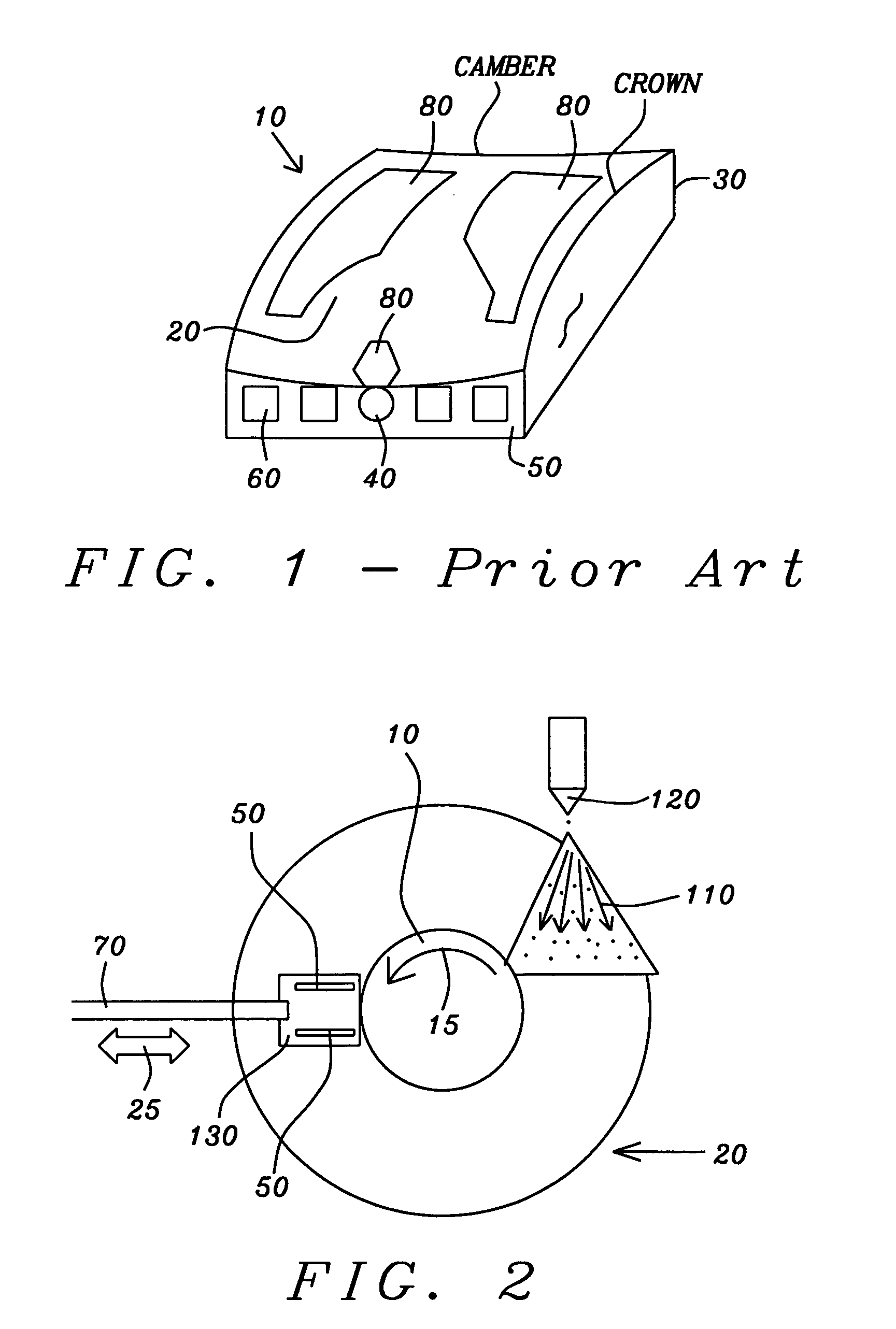
[0023] Looking now at FIG. 2, there is seen a schematic overhead view of the apparatus used to achieve the objects of the present invention. It is assumed that the contour lapping has already occurred. The compliant, porous CMP pad (20) is adhesively bonded to the surface of a rotating lapping baseplate (10) that is partially shown. The curved arrow (15) indicates the rotation direction of the baseplate.
[0024] A plurality of row bars, a row bar being an uncut linear array of sliders (50), only two row bars being shown here, is each then mounted on a polyurethane rubber strip (beneath each row bar and invisible in this view) that is affixed to the underside of a weighted lapping fixture (130) positioned above the lapping plate. Note, the row bars are shown here to indicate their orientation, but they would not be seen since they are beneath the fixture. The row bars will be flattened against the fixture for the CMP process, although they may have been slightly curved for the purpose of contour lapping, i.e., forming a crown / camber contour on the ABS, which was carried out before this CMP process. The contour lapping occurs before the CMP process. It is the CMP process that creates the recession of the alumina overcoat on the already contoured sliders.
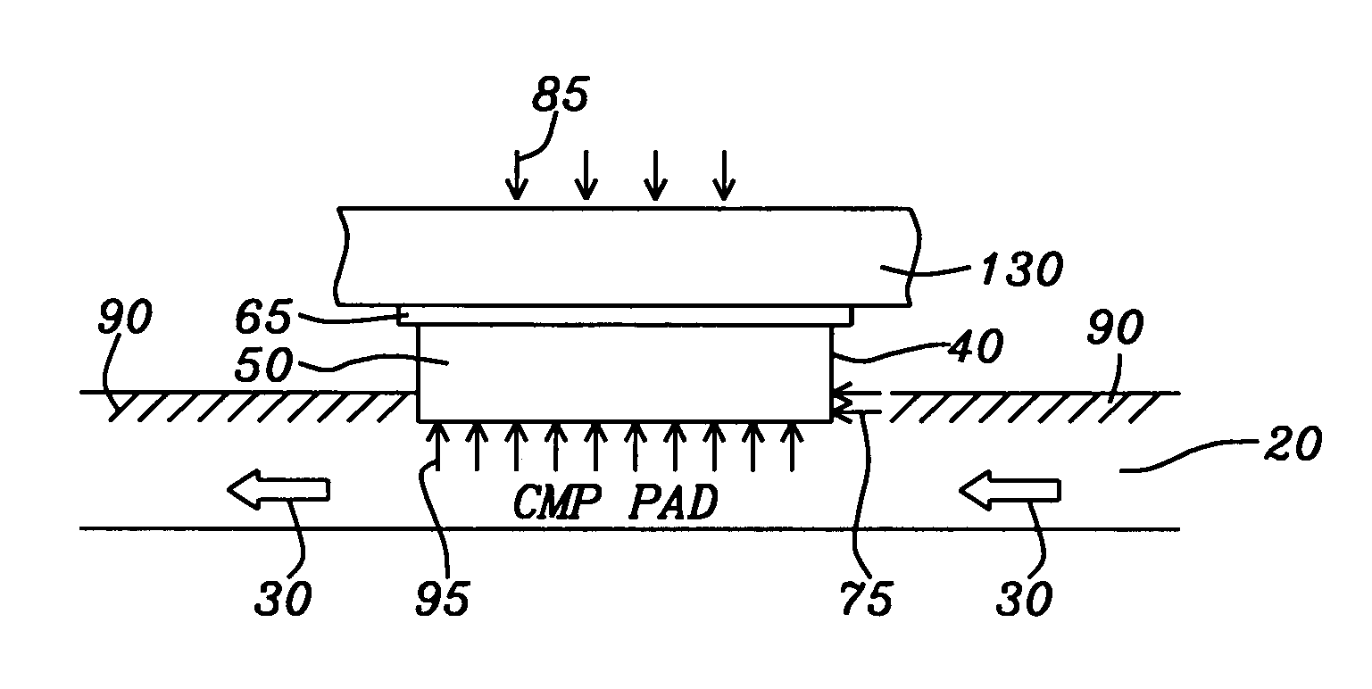
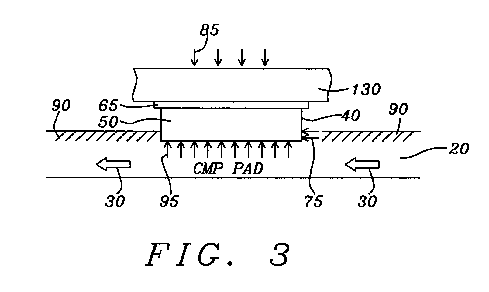
[0025] As will be seen in the following figure, FIG. 3, the ABS of the sliders are all in contact with the surface of the compliant porous CMP pad, compressing the pad (arrows (95) in FIG. 3) because of the weight (arrows, (85) in FIG. 3) of the lapping fixture. Returning to FIG. 2, the lapping fixture is capable of a vibratory translational motion produced by an oscillating guide arm (70), the motion (double ended arrow (25)) being in the radial direction relative to the circular lapping plate. The weighted fixture forces the ABS of each row bar and of the sliders within that row bar into the compliant pad and the pad, thereby conforms to the ABS shape. The sliders are arranged along the row bar so that their lengths, as measured along the crown, are perpendicular to the length of the row bar. The circular lapping plate is then set in rotational motion and the lapping fixture is set into oscillatory motion. During this process, the compliant pad is continuously wet by spraying with an aqueous alkaline solution (110) that acts as an etchant / lubricant that will soften the surface of the slider materials so that they can be removed in conjunction with the lapping / polishing process being produced by the motion of the slider against the rotating compliant pad. The aqueous solution is sprayed from the nozzle (120) of a separate pump and spray unit, mounted in situ, adjacent to the lapping plate. The resulting chemical reaction relies on the pH of the lubricant and the removal rate of the softened material relies on the very slight degree of abrasion resulting from the polymer solution pre-deposited on the pad.

Problems solved by technology

During the writing of data on the disk, current flows through the coil in alternating directions, which generates a relatively significant amount of heat.
With flying heights being already extremely low to enable accurate resolution of the narrow disk tracks, thermal protrusion can eventually result in a physical contact between the disk surface and the ABS plane.
This contact can move the slider off its target track, can cause damage to the slider assembly, can damage the disk surface and / or cause a permanent loss of data.
Within the description of the method, the use of rotating lapping plates in the prior art is discussed and it is noted that they produce problems leading to degraded head performance.

Method used


Image

  • Method for controlling overcoat recession in a magnetic thin film head
  • Method for controlling overcoat recession in a magnetic thin film head
  • Method for controlling overcoat recession in a magnetic thin film head

Examples


Embodiment Construction

[0030] The preferred embodiment of the present invention teaches a method of chemical / mechanical (CMP) polishing the ABS of a slider, using a compliant CMP pad whose surface has been rendered porous and formed into a polymeric matrix by a polymeric pre-treatment. The nature of the pad surface and its pre-treatment is fully described below.

[0031] During the application of the process, the compliant porous CMP pad is additionally sprayed with an aqueous alkali lubricant solution. The alkali lubricant softens surface coatings of Al2O3 that overcoat and cover portions of the slider surface and the moving, compressive contact of the ABS with the surface of the compliant pad is sufficient to remove the softened material in a slow and controlled manner without the use of abrasive polishing compounds. In this way, a controlled recession of the oxide surface coating is obtained and thermal protrusion of the oxide at a later time during actual device operation in a hard disk drive (HDD) is e...


PUM

PropertyMeasurementUnit
temperaturesaaaaaaaaaa
thicknessaaaaaaaaaa
heightaaaaaaaaaa

Abstract

The overcoat of a slider (alumina) is recessed relative to the slider ABS by a non-abrasive CMP process sufficiently to prevent thermal protrusion of the overcoat during subsequent slider use in a hard disk drive. The CMP process involves the oscillatory and rotational compressional contact between the ABS surface of the slider and a polymerically pre-treated compliant pad that is sprayed by an aqueous alkali lubricating solution having a pH between about 9 and 10. The overcoat is thereby also softened by the lubricating solution and removed by the compressional contact and no use of abrasives is required.

Description

BACKGROUND OF THE INVENTION [0001] 1. Field of the Invention [0002] This invention relates to the fabrication of thin film magnetic heads and particularly to a CMP planarization technique for controlling overcoat and pole tip recession of such a head relative to a slider surface. [0003] 2. Description of the Related Art [0004] A hard disk drive (HDD) uses an encapsulated thin film magnetic read / write head, called a slider, to read and write data on a magnetic medium or storage disk. FIG. 1 is a schematic illustration of such a device as is used in the prior art and whose improvement is the object of the present invention. The slider (10) has a pre-patterned air-bearing surface (ABS) (20) and is mounted on a head gimbal assembly (HGA) (not shown) that is activated by a mechanism and control circuitry to position the slider at various positions along the magnetic tracks on the disk (not shown). As the disk is rapidly rotated by a spindle motor (not shown), hydrodynamic pressure causes...

Claims


Application Information

Patent Timeline
Patent Type & Authority Applications(United States)
IPC IPC(8): G11B5/60
CPCG11B5/102Y10S438/976G11B5/3163G11B5/3169G11B5/3173G11B5/6005Y10T29/49043Y10T156/1082Y10T29/49052Y10T29/49041Y10T156/1116Y10T29/49798Y10T29/49046Y10T29/49048G11B5/3136G11B5/127G11B5/31G11B21/21
Inventor JOSE, WINSTONAYALA, RUDYMAHADEV, NIRAJ
Owner SAE MAGNETICS (HK) LTD
Why Eureka
Try Eureka