Voltage control and harmonic minimization of multi-level converter

a multi-level converter and voltage control technology, applied in the field of power generation systems, can solve the problems of harmonic waveforms always representing loss, harmonic waveform generation is particularly expensive in terms of power loss, and the diode rectifier acts as a non-, so as to minimize the generation of harmonics

Active Publication Date: 2007-05-17
HAMILTON SUNDSTRAND CORP
View PDF18 Cites 17 Cited by
  • Summary
  • Abstract
  • Description
  • Claims
  • Application Information

AI Technical Summary

Benefits of technology

[0009] The present invention relates to a system and method for controlling the fundamental voltage of a multi-level converter, while minimizing the generation of harmonics. In particular, the present invention includes a controller that determines a desired fundamental voltage magnitude. The controller combines a first pattern of pulses with a second pattern based on the desired fundamental voltage magnitude to generate a third pattern of pulses. The controller delivers voltage waveforms to active components within the active controller based on the third pattern of pulses, such that application of the voltage waveforms results in the desired fundamental voltage magnitude and phase being generated.

Problems solved by technology

However, diode rectifiers act as a non-linear load, only conducting or distributing current when the voltage across the respective diodes is positive.
Only current associated with the fundamental waveform produces real power, whereas, harmonic waveforms always represent a loss to the AC generator or the system as a whole.
In particular, for passive rectifiers, generation of 5th and 7th level harmonics are particularly expensive in terms of power loss.
Solving complicated transcendental equations is required to determine the pulse width of each switching event in order to control the DC output voltage to a desired level, making real time control of the DC output voltage difficult.
Furthermore, as active rectifiers are introduced into systems having increasing power levels, the high power switching devices required to handle high power currents and voltages incur high switching losses.
Therefore, systems that use a large number of switching events to reduce harmonic distortion or effectuate output voltage control incur high switching losses.
However, these schemes require complex calculations that also make real time control of the output voltage difficult to maintain.
Reducing the number of switching events in order to avoid the associated high switching costs typically results in a significant increase in lower order harmonics (specifically the high energy 5th and 7th level harmonics), resulting in an increase of rotor losses in the generator.
Large (and therefore expensive) filtering components would be required if lower order harmonics cannot be removed.
Therefore, a tradeoff exists between the switching losses associated with minimizing harmonics and facilitating control of the DC output voltage, and the cost of employing filters to remove the harmonic distortion.
The multilevel inverter / rectifier, which requires more active switching components, increases the complexity of switching schemes used to reduce harmonic distortion.
While the above discussion focused on rectifiers, the same issues and problems exist for invertors, because the only difference between the two is the direction of power.

Method used


Image

  • Voltage control and harmonic minimization of multi-level converter
  • Voltage control and harmonic minimization of multi-level converter
  • Voltage control and harmonic minimization of multi-level converter

Examples


Embodiment Construction

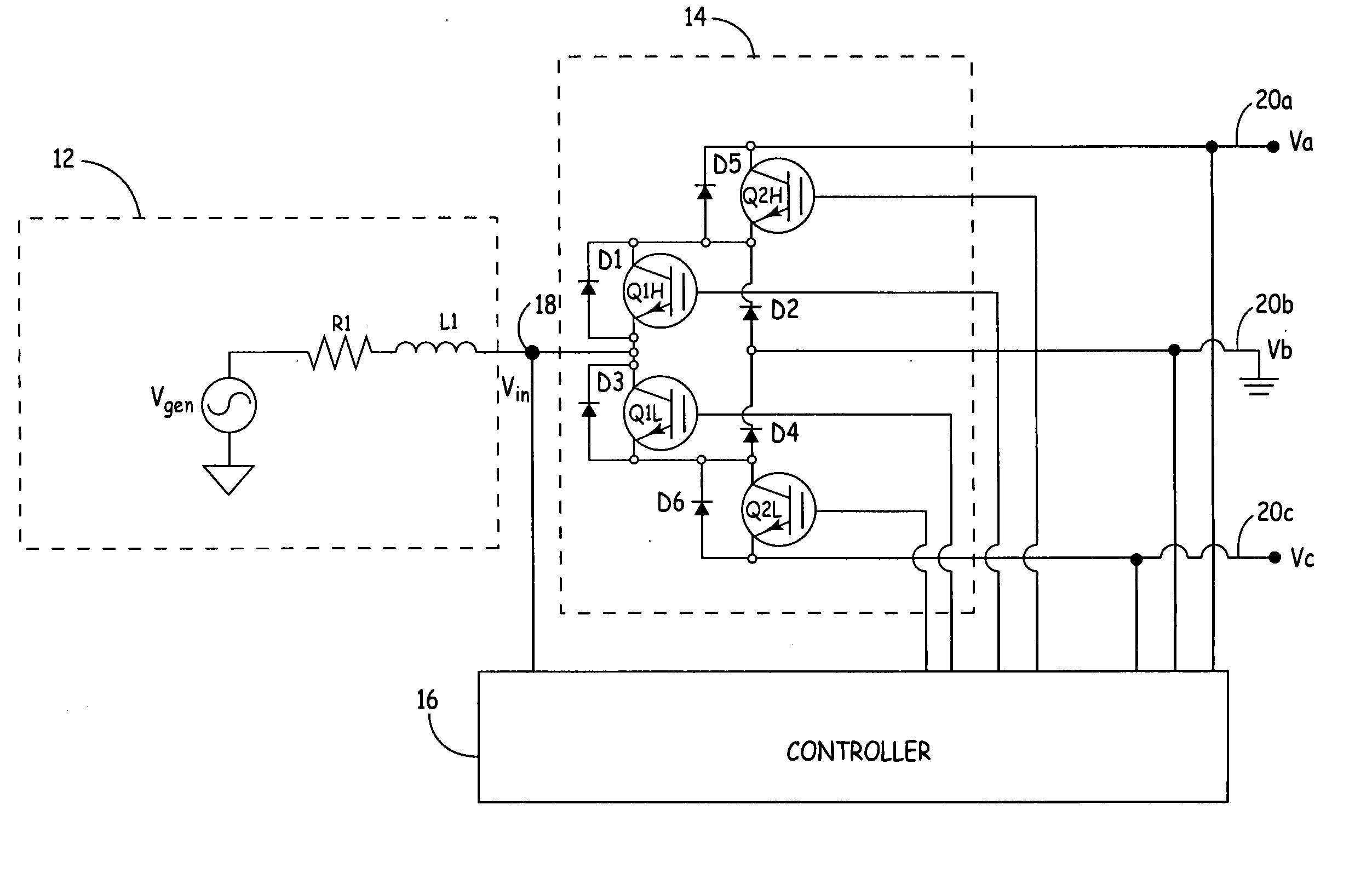
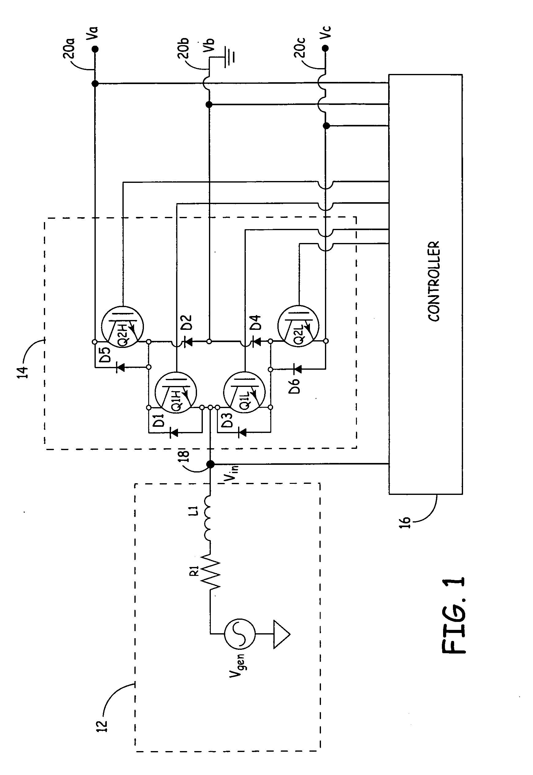
[0014]FIG. 1 shows a circuit diagram of generator / motor 12, three-level converter 14, and controller 16. To simplify the remainder of the description, the present invention is described in terms of three-level converter 14 operating as a rectifier. If three-level converter 14 operates as a rectifier, then node 18 can be described as input voltage Vin, and terminals 20a, 20b, and 20c can be described as DC output voltage Va, Vb, and Vc (in the case of an inverter, node 18 represents the output voltage, and terminals 20a, 20b, and 20c would act as the DC input). If three-level converter 14 were operating as an inverter (converting DC power to AC power) then generator / motor 12 would be treated as a motor. Therefore, throughout this description, generator / motor 12 will be described as generator 12. As discussed above, the direction power flows through converter 14 dictates whether three-level converter 14 operates as a rectifier or inverter. To further simplify the description, only the...


PUM


Abstract

A controller applies a pattern of pulses to switching elements within a multi-level controller to effectuate control of the fundamental voltage magnitude and phase associated with the converter, as well as providing harmonic minimization of the 5th and 7th level harmonics. The controller combines a first pattern of pulses with a second pattern of pulses phase shifted by an amount based on the desired fundamental voltage magnitude to create a third pattern of pulses. The controller applies a phase shift to the third pattern of pulses based on the desired fundamental voltage phase. The controller supplies switching control waveforms to active components within the multi-level controller based on the phase shifted third pattern of pulses such that the desired fundamental voltage magnitude and phase is generated and selected harmonics are minimized.

Description

BACKGROUND OF THE INVENTION [0001] Commonly used in power generation systems, converters are devices that either convert an alternating current (AC) signal into a direct current (DC) signal (rectifier), or a DC signal to an AC signal (inverter). Whether a converter is being used as a rectifier or an inverter is dependent on the direction power is flowing through the converter. A typical power generation system may include a generator for producing an AC signal, an AC-DC converter (or rectifier), a DC link, a DC-AC converter (or inverter), and a load. The AC signal generated by the generator is provided to the AC-DC rectifier, which provides a rectified signal to the DC link. Active control of the AC-DC rectifier helps maintain a constant DC output voltage. Furthermore, the DC link can include capacitive elements or filters that also help maintain a constant DC voltage level at the DC link. The DC link provides DC voltage to the load, which may be a DC-AC inverter or other DC load. [...

Claims


Application Information

Patent Timeline
Patent Type & Authority Applications(United States)
IPC IPC(8): H02M1/12H02M7/5387
CPCH02M7/487H02M1/12
Inventor ROMENESKO, CHARLES J.
Owner HAMILTON SUNDSTRAND CORP
Why Eureka
Try Eureka