Signal decoding method and device, and signal storage system

a signal and signal technology, applied in the field of decoding signals, can solve problems such as the inability to detect errors in decoding signals

Inactive Publication Date: 2007-05-17
ROHM CO LTD
View PDF1 Cites 39 Cited by
  • Summary
  • Abstract
  • Description
  • Claims
  • Application Information

AI Technical Summary

Benefits of technology

[0007] The present invention has been made in view of the above described circumstances, and an overall object thereof is the formation of a check matrix (parity check matrix) that can suitably detect errors.

Problems solved by technology

However, there are cases in which, according to the structure of the check matrix (parity check matrix), some errors occurring in the decoded signals cannot be detected.

Method used


Image

  • Signal decoding method and device, and signal storage system
  • Signal decoding method and device, and signal storage system
  • Signal decoding method and device, and signal storage system

Examples


Embodiment Construction

[0042] The invention will now be described by reference to the preferred embodiments. This does not intend to limit the scope of the present invention, but to exemplify the invention.

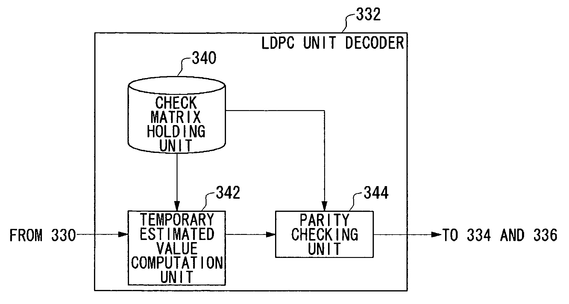
[0043] The present embodiment describes detection of errors generated when LDPC decoding of signals, that is, data, read from a magnetic disk device, is carried out. Specifically, by arranging linearly dependent columns at positions that are mutually non-adjacent, to compose a check matrix (parity check matrix), multiplication of all linearly dependent columns, at positions where burst errors occur, is avoided. In addition, in this way, detection of these burst errors is realized.

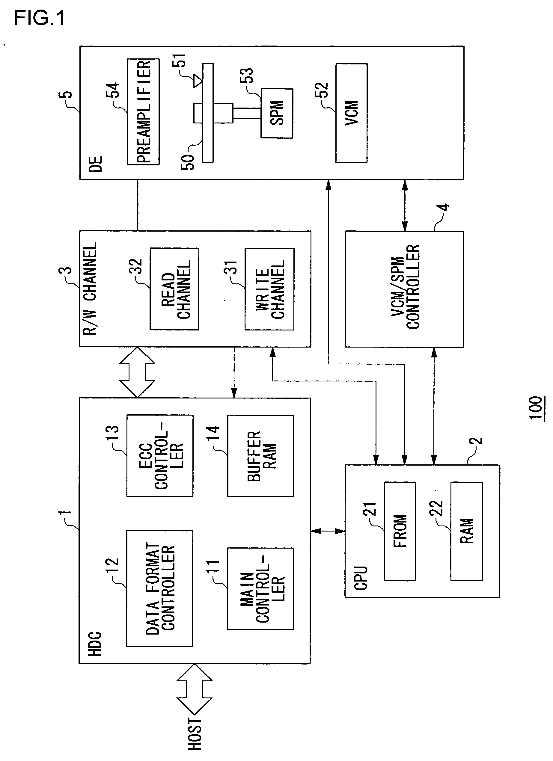
[0044]FIG. 1 is a view showing a configuration of the magnetic disk device 100. The magnetic disk device 100 of FIG. 1, broadly divided, includes a hard disk controller 1 (below, abbreviated to HDC 1), a central processing unit 2 (below, abbreviated to CPU 2), a read-write channel 3 (below, abbreviated to R / W channel 3), a vo...


PUM


Abstract

An LDPC unit decoder included in a signal decoding device is provided with a parity checking unit that is a multiplier for performing multiplication of a check matrix (parity check matrix) and temporary estimated values of an encoded signal, computed by a temporary estimated value computation unit. A check matrix (parity check matrix) holding unit holds the check matrix (parity check matrix). If s and t are natural numbers, s≧t≧2, among s columns extracted from this check matrix (parity check matrix), t columns or less have a linearly independent relationship. These s columns are multiplied at locations where error occurrence frequency is relatively high, with regard to the temporary estimated values. According to this mode, the matrix is composed to include t columns that are linearly independent, that is, t columns that are not linearly dependent. In this way, in a decoded signal series, when errors occur at t locations, since it is possible to avoid multiplying all the linear dependent columns at locations where errors occur, errors with a relatively high frequency of occurrence can be preferably detected.

Description

BACKGROUND OF THE INVENTION [0001] 1. Field of the Invention [0002] The present invention relates to technology for decoding signals that have been encoded. [0003] 2. Description of the Related Art [0004] When encoded signals are decoded, detection and correction of errors due to noise or the like are carried out. As one code for encoding signals, for example, low density parity check (expressed as LDPC below) code may be cited. When a signal encoded using the LDPC code is decoded (LDPC decoding), a decoded signal is multiplied by a check matrix (parity check matrix). In this way, detection of errors occurring with decoded signals is possible. Various methods have been proposed as methods of composing this check matrix (parity check matrix). For example, Patent Document 1 discloses a method of composing the check matrix (parity check matrix) in which a part of a matrix, defined according to a definition of a check matrix (parity check matrix) related to array codes, is modified to a...

Claims


Application Information

Patent Timeline
Patent Type & Authority Applications(United States)
IPC IPC(8): H04L27/00
CPCG11B20/10055G11B20/1866G11B2020/185H03M13/1102H03M13/6343
Inventor ESUMI, ATSUSHIMIZUNO, HIDEMICHI
Owner ROHM CO LTD
Why Eureka
Try Eureka