Linear Compressor
a compressor and linear technology, applied in the direction of positive displacement liquid engine, pump components, piston pump, etc., can solve the problems of deterioration of reliability, high risk, and inability of linear compressor to achieve improved constant compression efficiency
- Summary
- Abstract
- Description
- Claims
- Application Information
AI Technical Summary
Benefits of technology
Problems solved by technology
Method used
Image

Examples
first embodiment
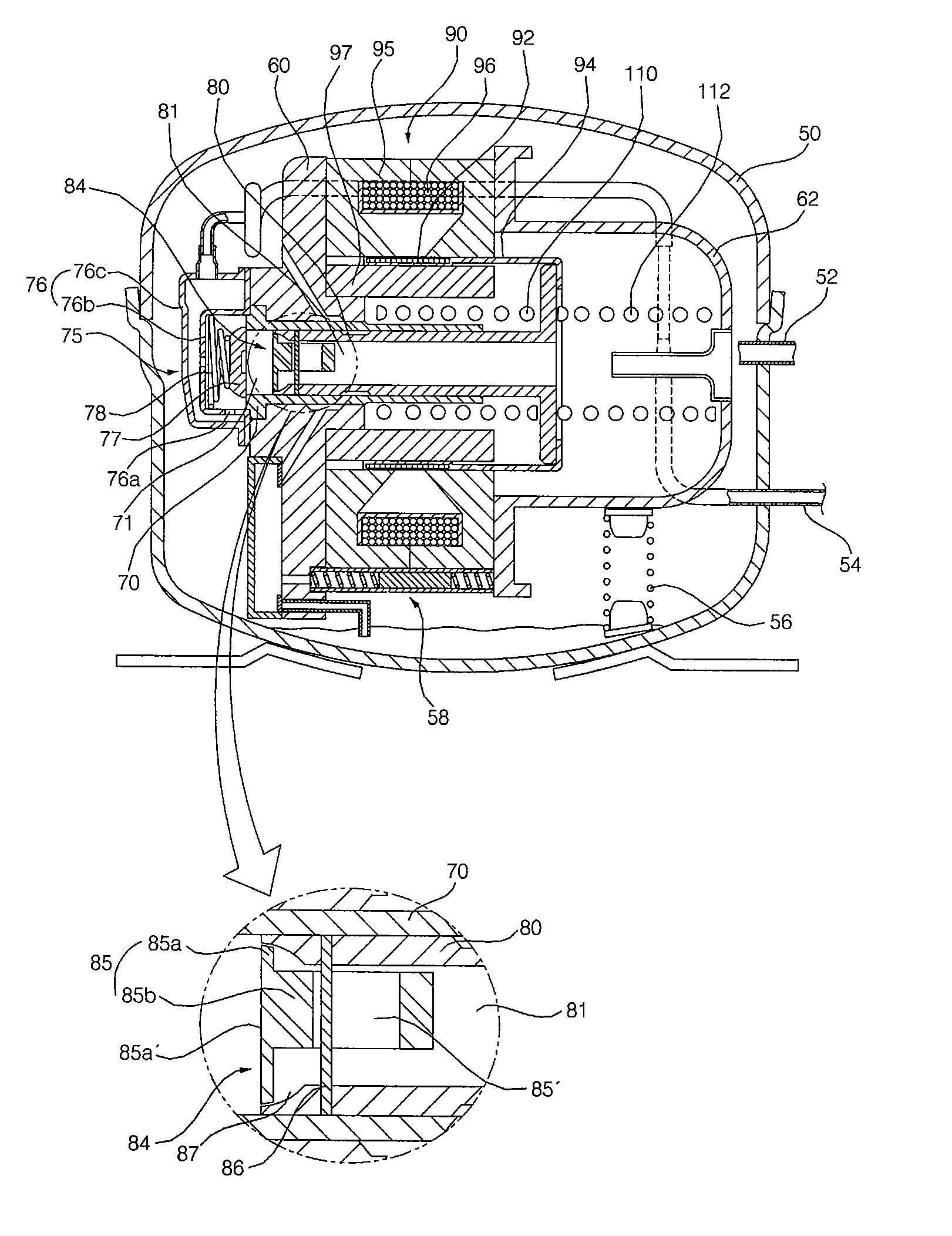
[0056] As shown in FIGS. 4 to 9, the linear compressor according to the present invention comprises a shell 50 configured to allow introduction and discharge of working fluid, a cylinder block 60 and a back cover 62 arranged in the shell 50, and a compression unit P provided between the cylinder block 60 and the back cover 62. The working-fluid, introduced into the shell 50, is compressed by a desired compression ratio while passing through the compression unit P, thereby being discharged in a high-pressure state.
[0057] A fluid suction pipe 52 is connected to the shell 50 such that the working-fluid is sucked into the shell 50 from an external station. Also, a fluid discharge pipe 54 is connected to the shell 50 such that the compressed working-fluid, discharged from the compression unit P, is guided out of the shell 50.
[0058] A damper 56 is mounted in the shell 50 to elastically support the compression unit P.
[0059] A lubricating oil pumping device 58 is arranged in the shell 50 ...
second embodiment
[0104]FIGS. 10 and 11 are configuration views of important parts of a linear compressor according to the present invention, FIG. 10 illustrating a retracted state of a piston included in the linear compressor, and FIG. 11 illustrating an advanced state of the piston.
[0105] As shown in FIGS. 10 and 11, the linear compressor according to the second embodiment of the present invention employs a suction valve 150, which includes a suction valve body 152 inserted in a suction path 161 of a piston 160 to move relative to the suction path 161, the suction valve body 152 having an elongated slot 150′ extending in a reciprocating movement direction of the piston 160, and a suction valve guide pin 154 fitted through the piston 160 and the slot 150′ of the suction valve body 152 to move relative to the slot 150′ while being fixed to the piston 160.
[0106] The suction valve body 152 may be divided into a head portion 152a disposed to protrude out of the suction path 161 of the piston 160, and a...
third embodiment
[0112]FIGS. 12 and 13 are configuration views of important parts of a linear compressor according to the present invention, FIG. 12 illustrating a retracted state of a piston included in the linear compressor, and FIG. 13 illustrating an advanced state of the piston.
[0113] As shown in FIGS. 12 and 13, the linear compressor according to the third embodiment of the present invention employs a suction valve 200, which includes a suction valve body 202 inserted in a suction path 211 of a piston 210 to move relative to the suction path 211, the suction valve body 202 having an elongated slot 200′ extending in a reciprocating movement direction of the piston 210, and a suction valve guide pin 204 fitted through the piston 210 and the slot 200′ of the suction valve body 202 to move relative to the slot 200′ while being fixed to the piston 210.
[0114] The suction valve body 202 may be divided into a head portion 202a disposed to protrude out of the suction path 201 of the piston 210, and a ...
PUM
 Abstract
Description
Claims
Application Information
 - Generate Ideas
- Intellectual Property
- Life Sciences
- Materials
- Tech Scout
- Unparalleled Data Quality
- Higher Quality Content
- 60% Fewer Hallucinations
Browse by: Latest US Patents, China's latest patents, Technical Efficacy Thesaurus, Application Domain, Technology Topic, Popular Technical Reports.
© 2025 PatSnap. All rights reserved.Legal|Privacy policy|Modern Slavery Act Transparency Statement|Sitemap|About US| Contact US: help@patsnap.com