[0013] An object of the present invention is to provide a separator for
fuel cells in which formation of the blister as described above can be prevented.
[0014] The present invention provides a separator for a fuel cell which will be in contact with a coolant, the separator including an electroconductive plate member, a primer layer formed on the surface of the plate member which contacts the coolant, and an insulation coating formed on the primer layer, in which a value (measured resistance value / calculated theoretical resistance value) of the primer layer is 95% or more. According to the present invention, the vapor component of the coolant that reaches the interface between the electroconductive plate member and the primer layer which constitute the separator, can be decreased, since a
fine structure, in which it is difficult for the coolant vapor to penetrate, as a primer layer can be realized. Therefore, the formation of
blisters in the primer layer can be prevented, even if there is a reduced temperature at a substrate part of the separator when
power output of the fuel cell is greatly decreased. In short, the vaporized component of the coolant is prevented from penetrating by making the primer layer finer, and thereby the formation of the blisters due to condensation can be prevented, even if the environment is at a temperature in which the vapor component condenses. In addition, density of a core which is necessary for condensing the vapor component of the coolant can be decreased by making the primer layer finer and by decreasing the density of the fine voids. This is also effective in the prevention of the condensation of the vapor component of the coolant in the interface between the primer layer and the plate member, thereby preventing the formation of blisters. In the case in which it is microscopically observed, the fine voids part is a non-adhered part in which the material which constitutes the primer layer is not adhered, and the fine voids can be also considered to be small voids which are sources for the formation of the blisters. According to the present invention, the non-adhered part in the above
microscopic observation is decreased and the primer layer having a certainly and uniformly adhered structure can be produced. This is also effective in decreasing the sources of formation of the blisters and in the prevention of formation of the blisters thereby.
[0019] In order to satisfy the conditions in which the value of the measured resistance value / the calculated theoretical resistance value in the primer layer is 95% or more, use of a method which repeats coating for forming the primer layer a number of times (so-called “
recoating”), is effective. The number of coating which is necessary can be experimentally determined by the value of the measured resistance value / the calculated theoretical resistance value. In addition, a method in which the
dilution rate is increased when the material which constitutes the primer layer is coated, and simultaneously, the number of times of coating is increased, is also effective. It is believed that the
recoating is effective since an effect for repairing defective portions formed in the last coating is repeated by the
recoating and number of the defective portions is decreased thereby. In addition, it is believed that the recoating of diluted coating material is effective, since the
viscosity of the coating material is reduced by
dilution in addition to the above effect of recoating, and the coating material is easily disposed into the defective portions. As another method for adjusting the value of the measured resistance value / the calculated theoretical resistance value, a method for controlling a temperature condition or a
humidity condition in the coating process and a method using ultrasonic vibrations, can be employed.
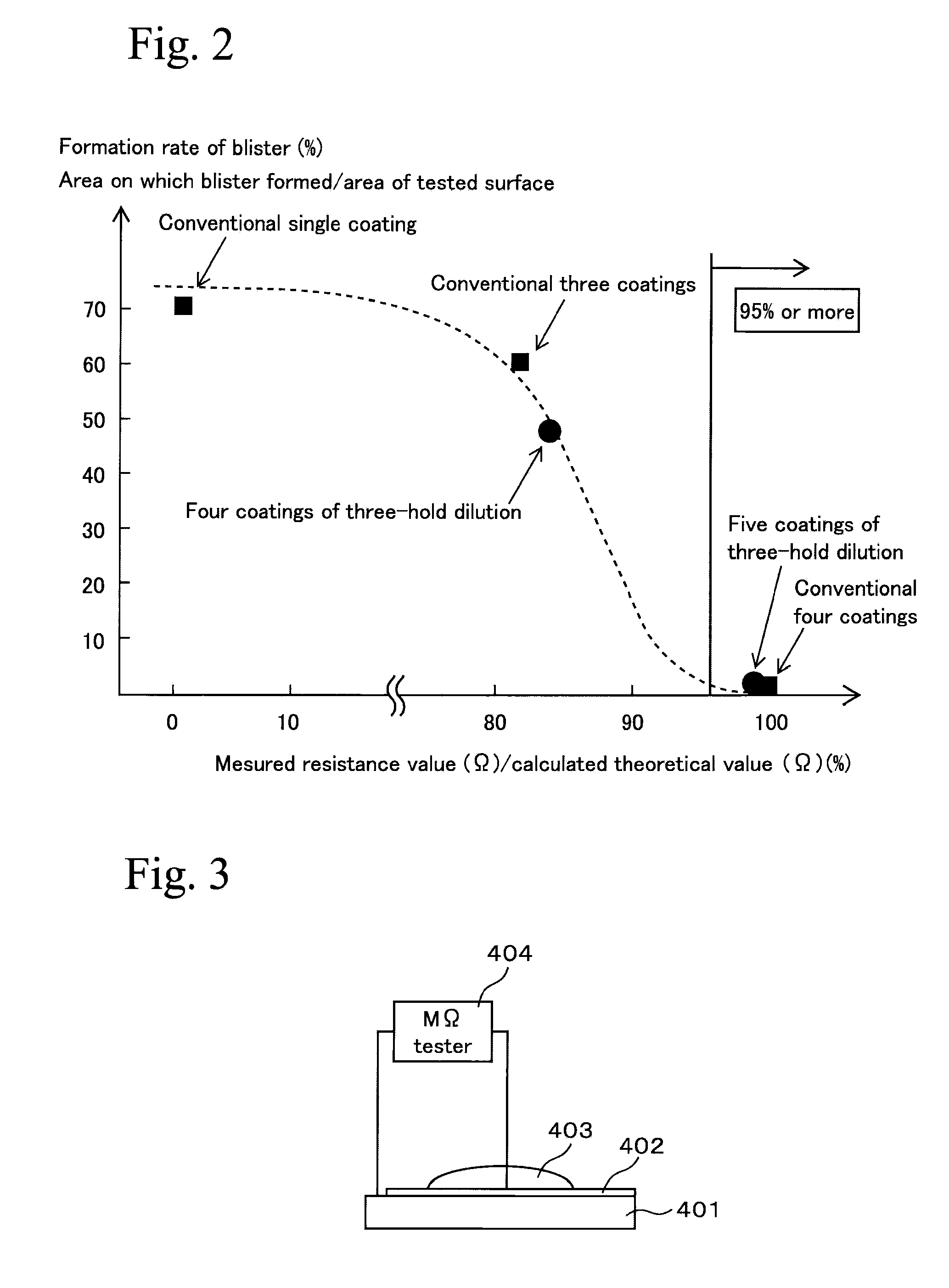
[0020] The measured resistance value in the present invention is measured as a resistance value in a thickness direction of the primer layer in a condition in which the
electrolyte penetrates. In the case in which the density of the fine voids in the primer layer is high, since substantial amounts of the
electrolyte penetrated, the path of
electrical conduction through the electrolyte is increased and the electrical resistance is reduced. As a result, the value of the measured resistance value / the calculated theoretical resistance value is decreased. Therefore, in the case in which the value of the measured resistance value / the calculated theoretical resistance value is low, vapor easily penetrates into the voids and the blisters are easily formed. This is clear from the data shown in the graph of FIG. 2. Thus, by the evaluation of the value of the measured resistance value / the calculated theoretical resistance value as an index, the density of the fine voids in the primer layer can be quantitatively measured, and it can be useful to prevent the formation of the blisters. Here, the electrolyte is not limited, so long as it is a neutral electrolyte such as a NaCl solution, etc.
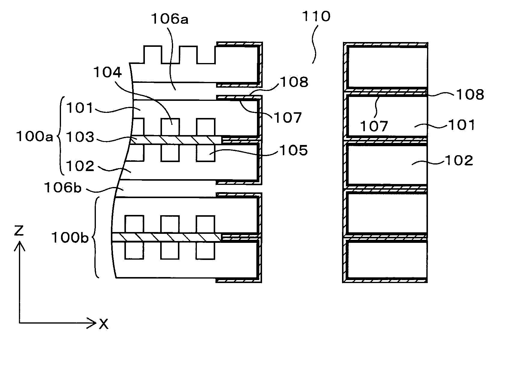
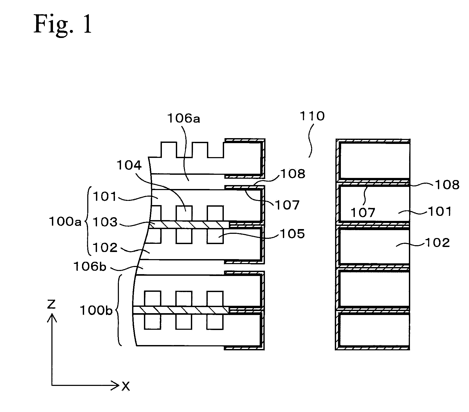
[0021] The present invention is suitable for application to a part in which the temperature of a plate member which constitutes the separator may be lower than the temperature of coolant which contacts an insulating coating of the part. That is, in the case in which the fixed portion of the separator is put in such a thermal environment, the vapor component of the coolant penetrating the insulating coating is easily condensed by transferring the heat of the portion to the plate member which constitutes the separator. By applying the present invention to the primer layer on such a portion, the primer layer on such a portion is made finer and the coolant vapor component can be prevented from penetrating into the primer layer on the portion. Then, components that occur due to condensation can be prevented from existing in the primer layer and the blisters can be prevented from forming, even if the thermal environment is at temperatures in which the coolant vapor component is condensed.
[0022] According to the present invention, the
fineness of the primer layer is ensured by setting the value of the measured resistance value / the calculated theoretical resistance value in the primer layer to be 95% or more, and thereby the vapor component of the coolant which causes the blisters to form can be prevented from penetrating into the primer layer. Consequently, the blisters can be prevented from forming and the
generating capacity can be prevented from being reduced due to the formation of the blisters.

