Twisting bifurcation delivery system

a delivery system and twisting technology, applied in the field of implantable medical devices, can solve the problems that many prior art stents are not wholly satisfactory for use, and achieve the effects of improving trackability during delivery, improving delivery accuracy, and simplifying the placement of stents

Inactive Publication Date: 2007-05-17
BOSTON SCI SCIMED INC
View PDF24 Cites 34 Cited by
  • Summary
  • Abstract
  • Description
  • Claims
  • Application Information

AI Technical Summary

Benefits of technology

[0015] The present invention contemplates new and improved apparatuses that simplify placement of a stent at the site of a vessel bifurcation. Embodiments of the present invention include systems that provide improved trackability during delivery as well as accuracy of delivery.

Problems solved by technology

Many prior art stents however are not wholly satisfactory for use where the site of desired application of the stent is juxtaposed or extends across a bifurcation in an artery or vein such, for example, as the bifurcation in the mammalian aortic artery into the common iliac arteries.

Method used


Image

  • Twisting bifurcation delivery system
  • Twisting bifurcation delivery system
  • Twisting bifurcation delivery system

Examples


Embodiment Construction

[0061] While this invention may be embodied in many different forms, there are described in detail herein specific preferred embodiments of the invention. This description is an exemplification of the principles of the invention and is not intended to limit the invention to the particular embodiments illustrated.

[0062] For the purposes of this disclosure, like reference numerals in the figures shall refer to like features unless otherwise indicated.

[0063] Depicted in the figures are various aspects of the invention. Elements depicted in one figure may be combined with, and / or substituted for, elements depicted in another figure as desired.

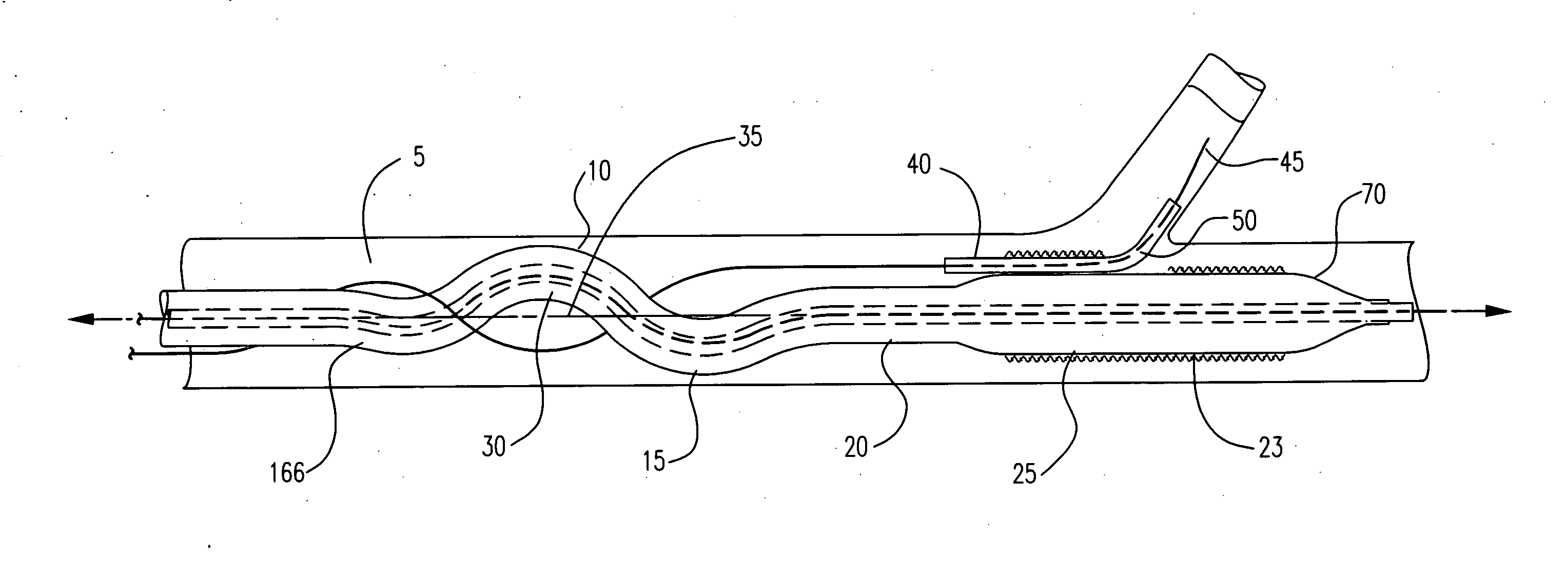
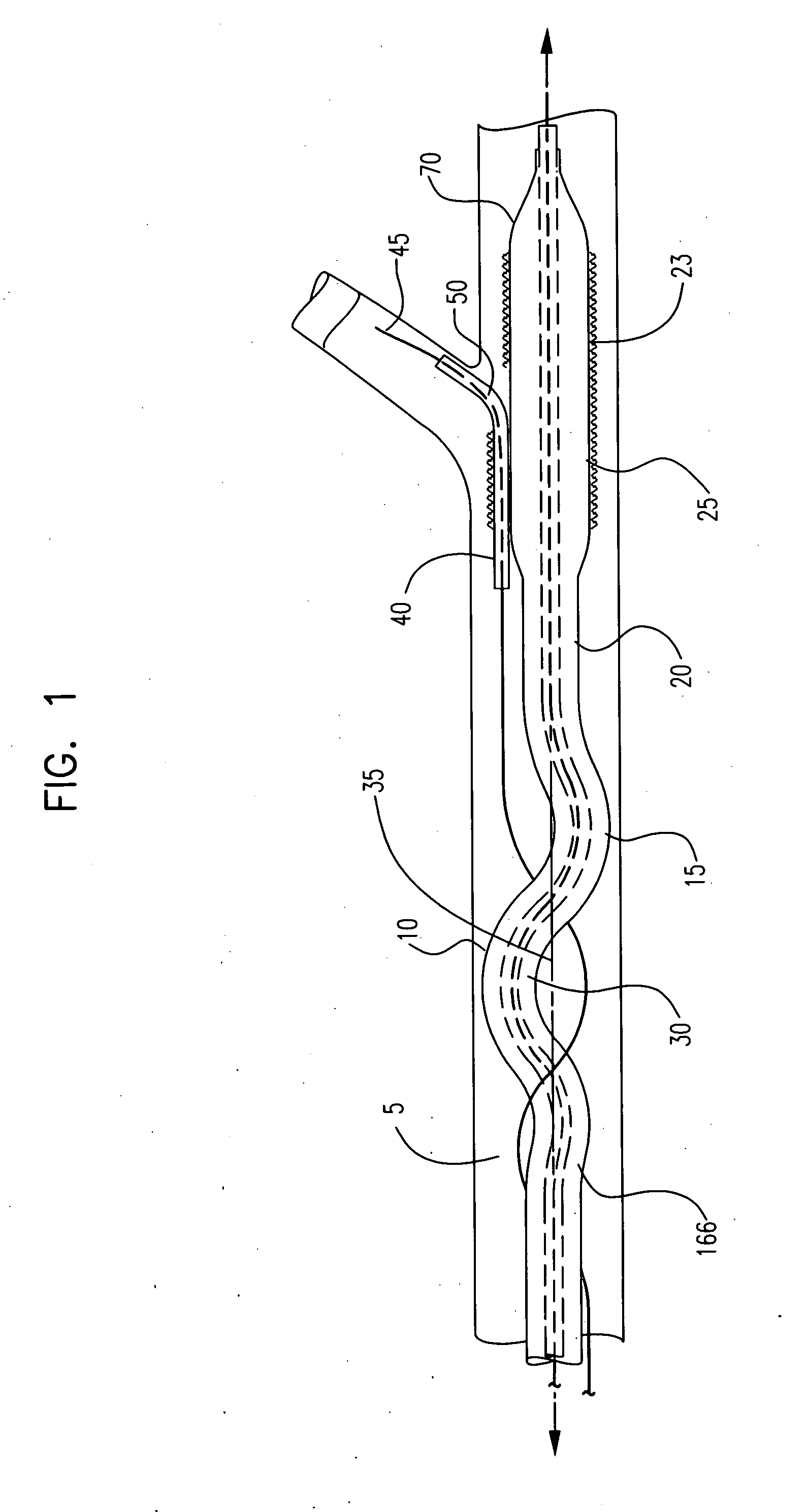
[0064]FIG. 1 shows an embodiment of the invention, a catheter system shown generally at 5. Catheter system 5 is comprised of a catheter 10, catheter shaft 15, expandable balloon 70, side branch guidewire housing 40, and side branch guidewire 45 which extends through side branch guidewire lumen 50. The distal region 20 of catheter shaft 15 define...


PUM


Abstract

A catheter system comprises a catheter having an elongate catheter shaft such that a portion of the catheter shaft proximal a stent retaining region defines at least one bend that is bent around the longitudinal axis of a vessel. The catheter also has a side branch guidewire housing, defining a side branch guidewire lumen, and a side branch guidewire that extends through the side branch guidewire lumen.

Description

CROSS-REFERENCE TO RELATED APPLICATIONS [0001] Not Applicable STATEMENT REGARDING FEDERALLY SPONSORED RESEARCH [0002] Not Applicable BACKGROUND OF THE INVENTION [0003] 1. Field of the Invention [0004] In some embodiments this invention relates to implantable medical devices, their manufacture, and methods of use. Some embodiments are directed to delivery systems, such as catheter systems of all types, which are utilized in the delivery of such devices. [0005] 2. Description of the Related Art [0006] A stent is a medical device introduced to a body lumen and is well known in the art. Typically, a stent is implanted in a blood vessel at the site of a stenosis or aneurysm endoluminally, i.e. by so-called “minimally invasive techniques” in which the stent in a radially reduced configuration, optionally restrained in a radially compressed configuration by a sheath and / or catheter, is delivered by a stent delivery system or “introducer” to the site where it is required. The introducer may...

Claims


Application Information

Patent Timeline
Patent Type & Authority Applications(United States)
IPC IPC(8): A61F2/06
CPCA61F2/954A61F2/958A61F2002/061A61F2002/065A61M25/04A61M2025/0058A61M2029/025
Inventor MERTENS, STEVEN P.ELIZONDO, DAVIDMALEWICZ, ANDRZEJHEIDNER, MATTEIDENSCHINK, TRACEE
Owner BOSTON SCI SCIMED INC
Why Eureka
Try Eureka