Optical element sealing structure, optical coupler, and optical element sealing method

Inactive Publication Date: 2007-05-24
SHARP KK
View PDF6 Cites 47 Cited by
  • Summary
  • Abstract
  • Description
  • Claims
  • Application Information

AI Technical Summary

Benefits of technology

[0015] In consideration of the above, an object of the invention is to provide an optical e

Problems solved by technology

This thus causes a problem that the sealing structure 1 cannot increase both the environmental resistance of the optical element 2 and the light transmission rate therefor.
This problem arises also in the fourth related-art technology.
In the second related-art technology, when the lens element 9 is implemented by glass, the lens element cannot be formed by molding so that the resulting optical coupler cannot be manufactured with low cost.
With this being the case, there are three problems of a difficulty in designing a lens that can lead to optical effects, a difficulty in manufacturing the glass lens 9 minute in size, and a difficulty in attaching to

Method used


Image

  • Optical element sealing structure, optical coupler, and optical element sealing method
  • Optical element sealing structure, optical coupler, and optical element sealing method
  • Optical element sealing structure, optical coupler, and optical element sealing method

Examples


first embodiment

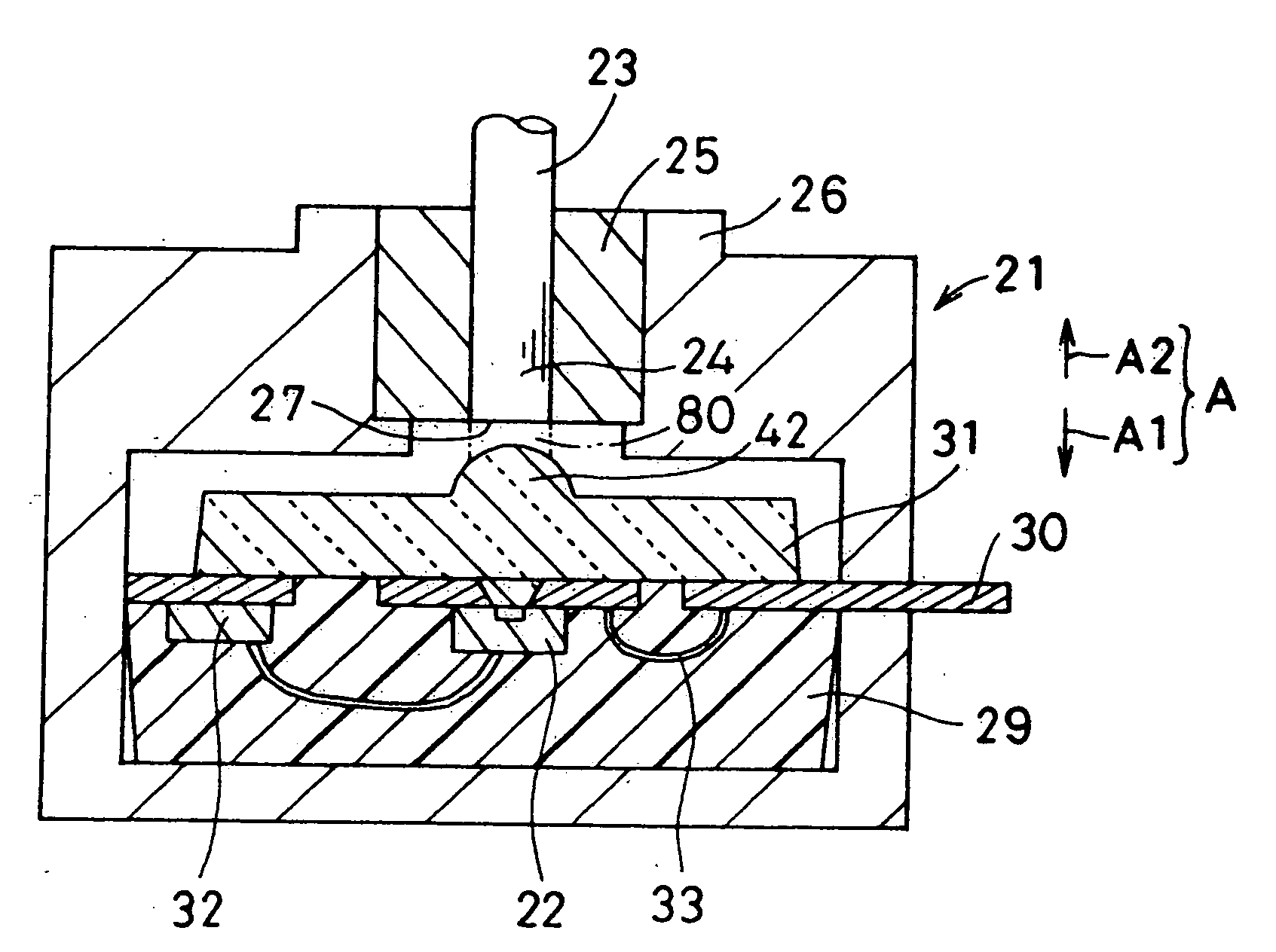
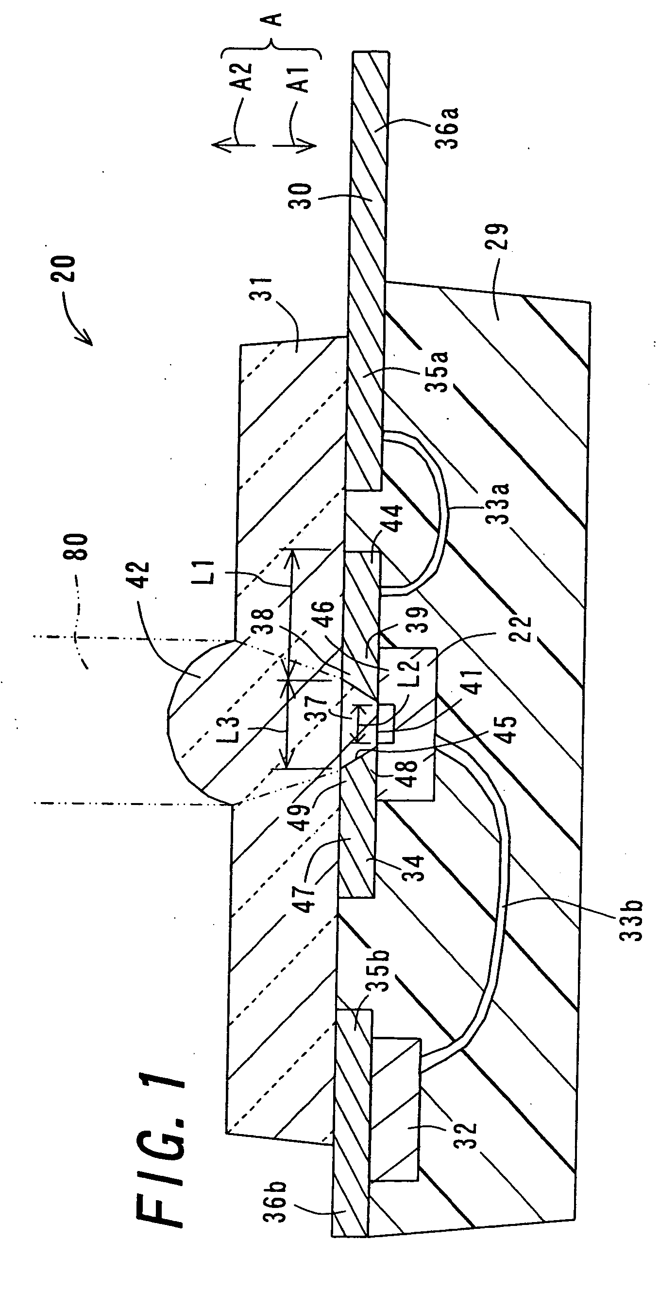
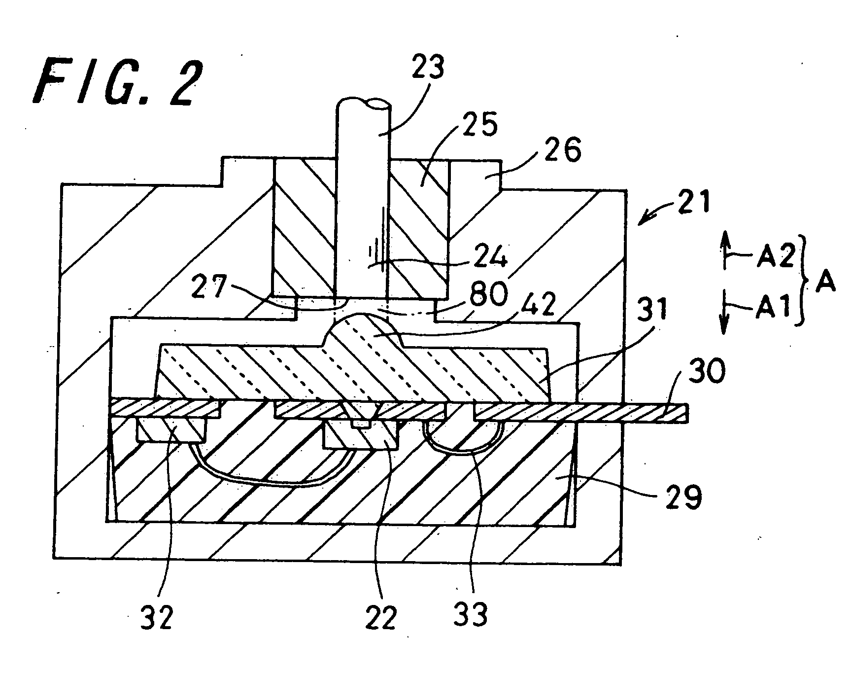
[0097]FIG. 1 is a cross sectional view of a sealing structure 20 in the invention, and FIG. 2 is a cross sectional view of an optical coupler 21 including the sealing structure 20. For optical communications, the optical coupler 21 establishes a connection between an optical element 22 and an optical fiber 23 to be ready for optical transmission, i.e., so-called optical coupling apparatus. The optical element 22 is a semiconductor with the optical function, and for example, is a light-emitting element such as a light emitting diode (LED, Light Emitting Diode), and a light-receiving element such as a photo diode (PD, Photo Diode).

[0098] The optical fiber 23 is a cable formed to be flexible and long in length. The optical fiber 23 serves as an optical transfer medium that transfers light from one end portion to the other end portion. That is, light coming from one end portion of the optical fiber 23 passes through the optical fiber 23, and exits from the other end portion of the optic...

fifth embodiment

[0188] The sealing structure 420 of the fifth embodiment can be formed by molding. In this case, as to the lead frame 30 to be attached, in the sealing body molding mold 60, a first mold 61 serving as the side in the other thickness direction A2 forms an internal space between the lead frame 30 and a second mold. In this state, by filling a sealing molding resin into the internal space of the mold, the sealing body 29 is formed. At this time, the first mold portion 61 abuts on the optical element mounting section 34 of the lead frame 30, and the distance from an outer peripheral portion of the abutting portion of the mold portion 61 to the light transmitting section 38 is set to the above-described separation distance L1. This prevents the sealing molding resin from finding its way to the light transmitting section 38. Further, because the optical element 22 never abuts on the first mold portion 61, the optical element 22 can be protected from any possible damage. When the sealing m...

sixth embodiment

[0201]FIG. 13 is a flowchart showing the manufacturing procedure of the sealing structure 520 of the FIG. 14 is a cross sectional view for illustrating the manufacturing procedure of the sealing structure 520. First of all, in step a0, after a designing process, e.g., outer diameter designing of the sealing structure 520, or wiring pattern designing of the lead frame 30, the procedure goes to step a1, and the sealing structure 520 is started to be manufactured.

[0202] In the manufacturing process, the procedure goes through steps a1 to a3 in order. Note here that steps a1 to a3 are similar to steps s1 to s3 of FIG. 3, and thus are not described again. When the sealing body 29 is completely molded in step a3, the procedure goes to step a4.

[0203] In step a4, using a dispenser or others, the adhesive 502 is filled into the aperture 37 of the optical element mounting section 34 and the aperture 104 of the sub mount 100. Once the adhesive 502 is through with filling thereinto, the proce...


PUM


Abstract

A sealing structure includes a lead frame having a light transmitting section, an optical element having an optical surface which is directed to the light transmitting section and is mounted on the lead frame in such a state that the optical element blocks the light transmitting section at its one end portion in an axis direction, and a sealing body that is formed in a region excluding an optical path and seals the optical element. By forming the sealing body in the region excluding the optical path, the light usage efficiency can be prevented from decreasing even when a material that can increase the environmental resistance is added to the sealing body. Further, since the optical element is mounted on the lead frame with its face down, the sealing structure can be easily formed even when the optical element is small-sized.

Description

TECHNICAL FIELD [0001] The present invention relates to an optical element sealing structure of sealing therein an optical element, and exemplarily, relates to a sealing structure of sealing therein an optical coupler for use for an optical communications link or others over which optical signals are transmitted and received using a transmission medium of optical fibers. BACKGROUND ART [0002] Optical couplers are used for optical communications between devices, in households, and in vehicles. The optical couplers are apparatuses for establishing an optical coupling between optical elements and optical fibers. For example, the optical elements are exemplified by a light emitting diode (LED, Light Emitting Diode), a photo diode (PD, Photo Diode), and the like. The optical coupler is of a sealing structure in which such an optical element is sealed by using a molding resin. [0003]FIG. 15 is a cross sectional view of a sealing structure 1 of a first related-art technology. In Japanese U...

Claims


Application Information

Patent Timeline
IPC IPC(8): H01L33/00H01L21/00H01L23/28G02B6/42H01L23/29H01L23/31H01L23/50H01L31/02H01L31/0203H01L31/0232H01L33/30H01L33/54H01L33/56H01L33/62H01L33/64H01S5/022
CPCG02B6/4206G02B6/423G02B6/4248H01L31/0203H01L31/0232H01L33/54H01L33/56H01L2224/48091H01L2224/48247H01L2924/01046H01L2924/01078H01L2924/01079H01L2924/19107H01L2924/3025H01L2924/00014H01L2924/01019H01L2924/01322H01L2924/12041H01L2224/48137H01L2924/1815H01L2924/181H01L2224/49107H01L2924/15151H01L31/02325H01L2924/00012
Inventor FUJITA, HIDEAKIIWAKI, TETSUOISHII, YORISHIGE
Owner SHARP KK
Why Eureka
Try Eureka