Space-variant waveplate for polarization conversion, methods and applications

a spacevariant wave and polarization conversion technology, applied in the field of polarized light, can solve the problems of inhomogeneous polarized light not being considered for use in many applications, null on-axis, and difficult control of which of the many possible azimuthal modes will be emitted

Inactive Publication Date: 2007-05-24
SPILMAN ALEXIS +1
View PDF5 Cites 153 Cited by
  • Summary
  • Abstract
  • Description
  • Claims
  • Application Information

AI Technical Summary

Benefits of technology

[0028] According to an embodiment of the invention, a polarization converter includes an optically transparent window having a clear aperture defined by opposing, polished faces and a periphery. The window is characterized by having an induced symmetric stress birefringence pattern over at least a portion of the clear aperture that is sufficient to produce an optical retardance equal to or greater than a quart...

Problems solved by technology

In the past, inhomogeneously polarized light has not been considered for use in many applications, including lithography and optical imaging systems, such as microscopes for the inspection of semiconductor wafers, phase shift masks and reticles.
Because CV beams have polarization vectors that are cylindrically symmetric about the optical axis, a phase vortex exists at the center of the beam, and an on-axis null results.
Unfortunately, it is not easy to control which of the many possible azimuthal modes will be emitted by the CCGSE laser.
As a result, the azimuthally polarized light produced using CCGSE lasers are of li...

Method used


Image

  • Space-variant waveplate for polarization conversion, methods and applications
  • Space-variant waveplate for polarization conversion, methods and applications
  • Space-variant waveplate for polarization conversion, methods and applications

Examples


Embodiment Construction

[0066] When possible, like reference numerals will be used to describe like parts among the various embodiments of the invention, with reference to the figures.

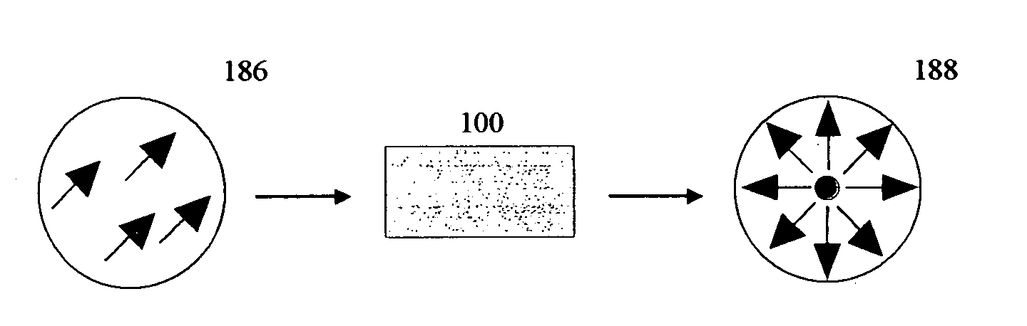
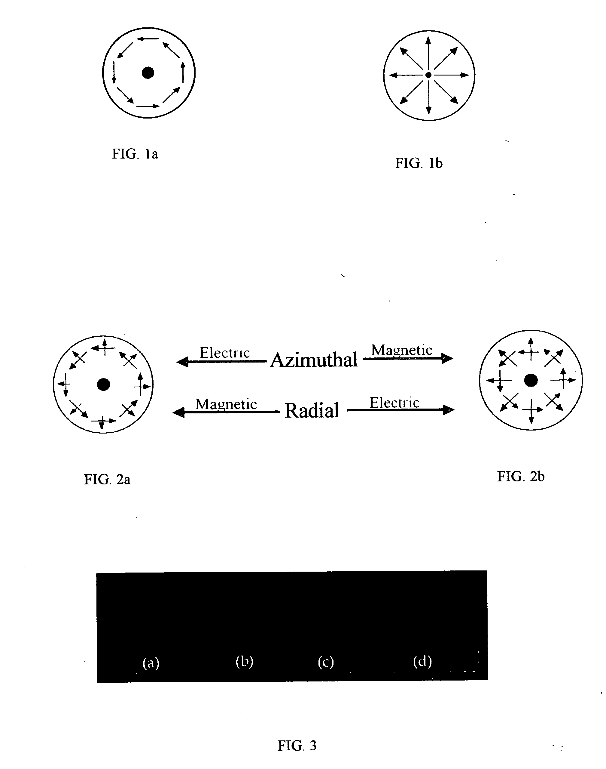
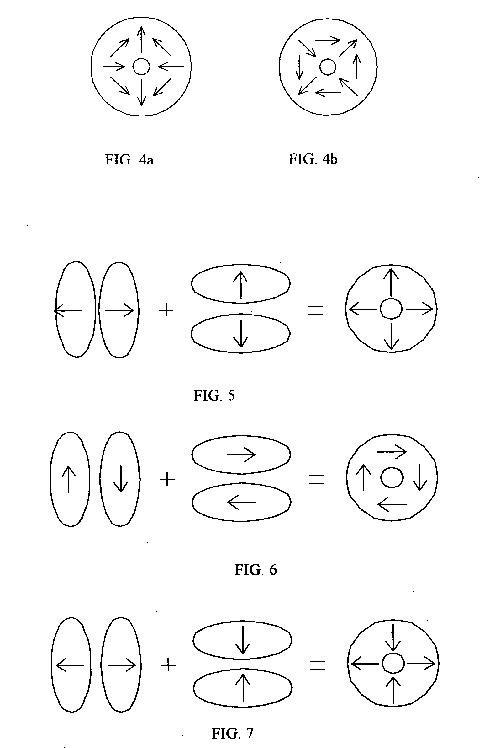
[0067] An embodiment of the invention is directed to a polarization converter that converts spatially homogeneously polarized light into spatially inhomogeneously polarized light having a fast axis orientation that varies in a smooth and continuous manner over a pupil aperture of the device upon propagation through the device.

[0068]FIG. 10 illustrates a polarization converter 100-1 according to an exemplary embodiment of the invention. The polarization converter 100-1 includes an optically transparent window 120 having a clear aperture 121 defined by opposing, polished faces 123, 125 and a periphery 127 (FIG. 11). In an exemplary aspect, the window 120 is cylindrical, having a diameter, ΦG, equal to 0.5 inches and a thickness, Th, equal to 0.375 inches. The exemplary window 120 is BK7 glass. Fused silica is an alternative w...


PUM


Abstract

Embodiments of the invention are directed to apparatus and methods for converting spatially homogeneously polarized light into spatially inhomogeneously polarized light having a fast axis orientation that varies in a smooth and continuous manner over a pupil aperture. A space-variant waveplate referred to herein as a polarization converter includes an optically transmissive window characterized by a symmetric stress birefringence that provides at least λ/4 retardance and, more particularly, λ/2 retardance over an annular region centered about the optical axis of the window. Structural embodiments of the polarization converter include a mechanical compression housing and a thermal compression housing. Radially and azimuthally polarized vortex beams including cylindrical vector beams and counter-rotating beams can be generated from uniformly plane polarized input beams propagating through the polarization converter. Low-order polarization vortex beams can be optically combined to produce higher-order scalar vortex beams. Embodiments of the invention are also directed to various optical illumination and imaging systems utilizing the apparatus and methods described herein.

Description

RELATED APPLICATION DATA [0001] This application claims the benefit of priority of Provisional Application Ser. No. 60 / 667,232 filed on Apr. 1, 2005, the entire disclosure of which is incorporated herein by reference.FEDERALLY SPONSORED RESEARCH [0002] Not applicable. BACKGROUND OF THE INVENTION [0003] 1. Field of the Invention [0004] Embodiments of the invention are most generally related to the field of polarized light, including its generation and conversion. More particularly, embodiments of the invention are directed to novel polarization conversion devices and methods, optical systems employing such devices, and applications utilizing such devices, methods and systems. [0005] 2. Description of Related Art [0006] Homogeneously polarized light can be thought of as light having a polarization state that is spatially uniform across the pupil of the polarizer. Linearly polarized light, that is, light for which the spatial orientation of its electric field lies entirely within one p...

Claims


Application Information

Patent Timeline
IPC IPC(8): G02B5/30
CPCG02B27/286G03F7/70566
Inventor SPILMAN, ALEXISBROWN, THOMAS G.
Owner SPILMAN ALEXIS
Why Eureka
Try Eureka