Transmission apparatus

a technology of transmission apparatus and transmission line, which is applied in the direction of electrical apparatus, digital transmission, baseband system, etc., can solve the problems of line demand growth accompanies risks, depletion of fiber-optic core lines, and lack of the ability to pass through the 8b/10b cod

Inactive Publication Date: 2007-05-24
HITACHI LTD
View PDF11 Cites 61 Cited by
  • Summary
  • Abstract
  • Description
  • Claims
  • Application Information

AI Technical Summary

Benefits of technology

[0015] In particular, the stuff synchronizer includes a stuff processing determination unit which has functionality for performing, upon execution of positive stuff or negative stuff processing, the positive/negative stuffing while avoiding generation of violation to 8B/10B code rules (abnormality of running disparity or “RD”) by

Problems solved by technology

However, in another aspect, such line demand growth accompanies risks as to the depletion of fiber-optic core lines for signal transmission via these broadband links.
In the prior art GbE multiplex device, the 8B/10B code is terminated at a time whenever a GbE signal is received, so it suffers from a problem as to the lack of an ability to pass through the 8B/10B code between client devices.
Unfortunately, this technique is also based on the use of the existing SONET/SDH technology.
Several information items must be transmitted in a rounded form, so this scheme is not able to realize complete or full transparency.
This results in neglect of the functions as to the retention of physical line quality and the quality monitoring, which are important roles of a layer-1 device.
Upon installation of prior art GbE multiplexing

Method used


Image

  • Transmission apparatus
  • Transmission apparatus
  • Transmission apparatus

Examples


embodiment 1

[0093]FIG. 11 shows, in block diagram form, a configuration of a Gigabit Ethernet (GbE) multiplexing apparatus in accordance with a first embodiment of this invention.

[0094] As shown herein, the GbE multiplexer device embodying the invention is generally made up of a predetermined number, N, of low-rate side received signal processing units 11 to in which receive N 8B / 10B-encoded GbE signals and convert them into electrical signals after extraction of a clock(s) and then apply thereto data processing for creation of a parallel data, N 8B / 10B code synchronizing units 21-2n which independently detect an 8B / 10B code synchronization pattern relative to a respective one of the above-noted N GbE signals that have been converted into the electrical signals and perform data bit alignment rearranging or sorting processing, stuff synchronizer units 31-3n for synchronizing N GbE signals that differ in frequency from one another in a range of + / −100 ppm in maximum into a single specific freque...

embodiment 2

[0142] Fixed assign of time slot (no port identifiers are necessary).

[0143] Turning to FIG. 27, a configuration of a Gigabit Ethernet (GbE) multiplexing apparatus in accordance with a second embodiment of this invention is illustrated in block diagram form.

[0144] This embodiment is characterized by having, in place of the port identifier inserters 31-3n and port identifier separator 140, a time slot assigning unit 150 and a time slot detection unit 160 along with a digital wrapper frame generator unit 170 and a digital wrapper frame detector unit 180, thereby to fixedly assign a location (time slot) at which the data of each port is mapped with respect to the phase of a frame of digital wrapper having a fixed length frame. Regarding the other arrangements, this embodiment is the same as the embodiment 1.

[0145] Although the description here assumes that an optical transport network (OTN) frame which is defined in ITU-T Recommendation G.709 is used as an example of the digital wrap...


PUM


Abstract

A transmission apparatus is disclosed, which performs positive/negative stuffing with 8-bit/10-bit (8B/10B) codes being kept intact while retaining the normality of 8B/10B codes and the continuity of running disparity (RD) without termination of 8B/10B codes of a plurality of Gigabit Ethernet (GbE) signals received. The apparatus then executes multiplexing and separation after synchronization of the plurality of signals, thereby achieving the “transparent” transport of management information which is contained in the 8B10B codes between user devices.

Description

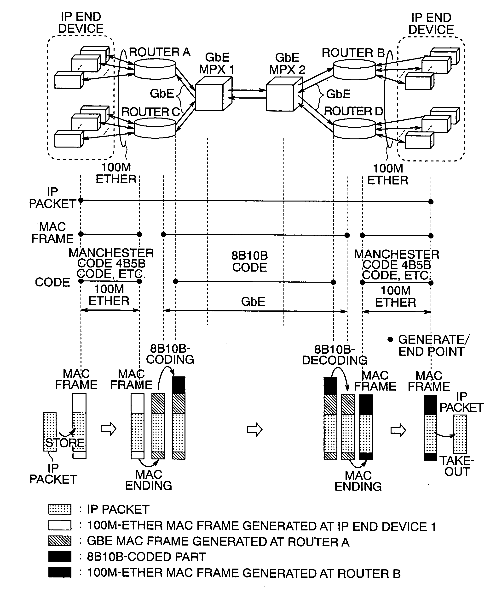
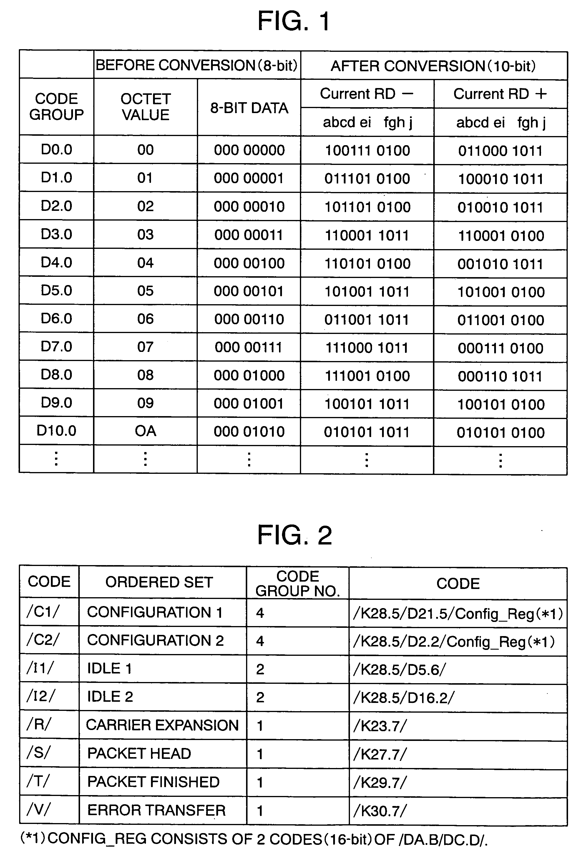
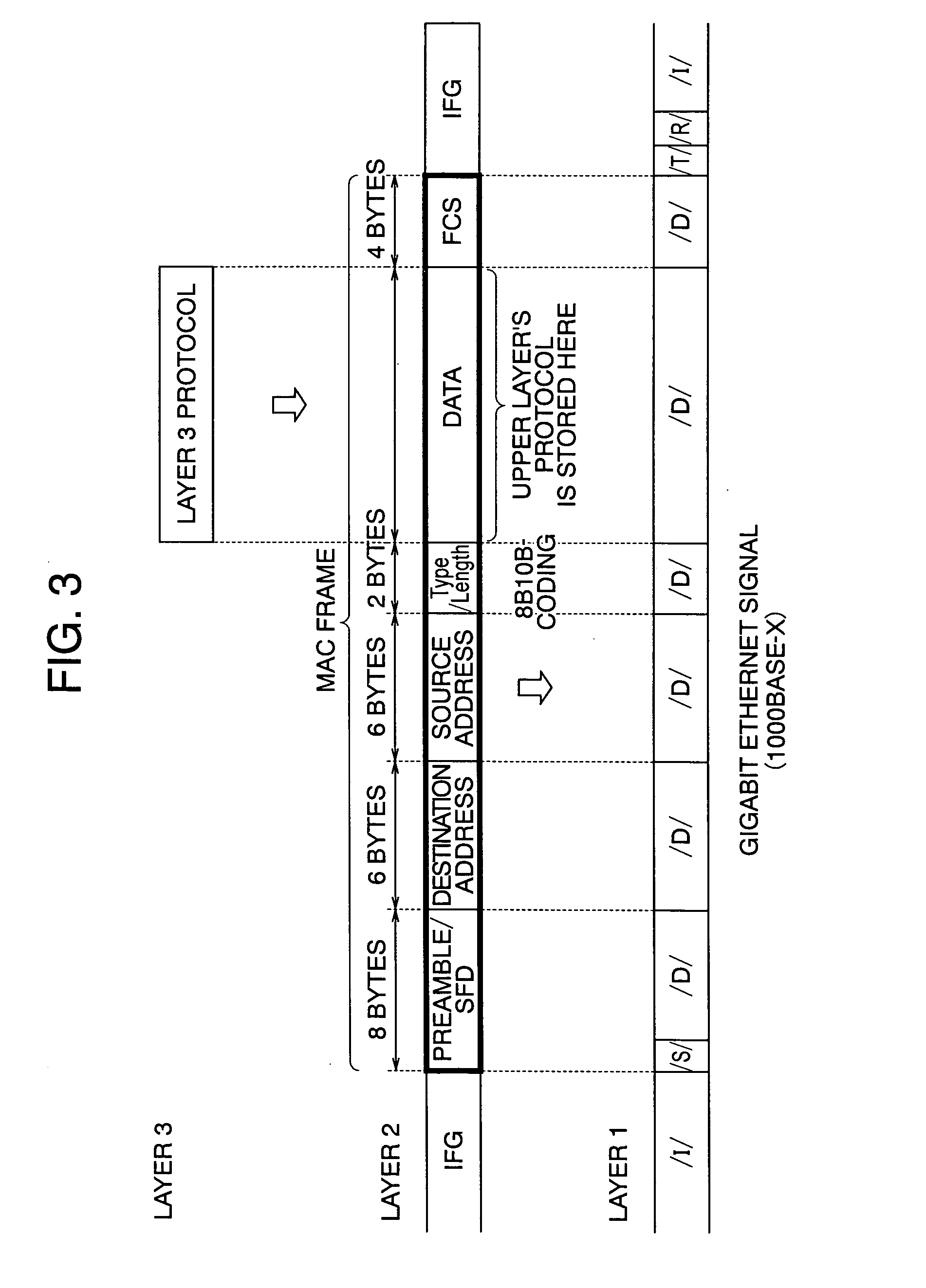
INCORPORATION BY REFERENCE [0001] The present application claims priority from Japanese application JP2005-299555 filed on Oct. 14, 2005, the content of which is hereby incorporated by reference into this application. BACKGROUND OF THE INVENTION [0002] The present invention relates to a transmission apparatus for multiplexing a plurality of signals which are transmitted based on 8B / 10B codes, such as Gigabit Ethernet signals or Fibre Channel signals. Gigabit Ethernet is a registered trademark and will be referred to as “Gigabit Ether” or “GbE” hereinafter. [0003] In recent years, broadband data communications lines including the Internet become widespread for home-use purposes also, and the demand for high-speed lines is growing with a central focus on IP traffic. To meet this demand, traditional major technologies in wide area networks (WANs), such as the synchronous optical network / synchronous digital hierarchy (SONET / SDH) and asynchronous transfer mode (ATM), are replaced by the ...

Claims


Application Information

Patent Timeline
IPC IPC(8): H04J3/00
CPCH04J3/07H04J3/1658H04J2203/0085H04J2203/0089H04L25/4908
Inventor ATSUMI, TOSHIYUKIMIYASAKA, EITA
Owner HITACHI LTD
Why Eureka
Try Eureka