Needle roller bearing, crank shaft supporting structure, and split method of outer ring of needle roller bearing

Inactive Publication Date: 2007-05-24
NTN CORP
View PDF16 Cites 23 Cited by
  • Summary
  • Abstract
  • Description
  • Claims
  • Application Information

AI Technical Summary

Benefits of technology

[0067] Since a load is not applied to the outer ring in the diameter direction according to the above methods, a deformed amount can be small in the vicinity of the split part. As a result, the needle roller can stably roll and a trouble can be prevented.
[0068] According to the present

Problems solved by technology

This complicates the incorporating operation procedures and needs a special member for preventing the retainer 114 from falling off in some cases, which increases the number of operation steps and an operation cost.
Furthermore, this step part becomes large as incorporating precision gets worse.
The abnormal sound becomes loud as the step part becomes large and as the bearing rotation is speeded up, which becomes a big problem for the bearing that supports the shaft rotating at high speed such as the crank shaft 101.
Furthermore, when the metals come in contact to each other, the contact part could be abraded and a lubricant agent could deteriorate because abrasion powder is mixed in.
Since th

Method used


Image

  • Needle roller bearing, crank shaft supporting structure, and split method of outer ring of needle roller bearing
  • Needle roller bearing, crank shaft supporting structure, and split method of outer ring of needle roller bearing
  • Needle roller bearing, crank shaft supporting structure, and split method of outer ring of needle roller bearing

Examples


Embodiment Construction

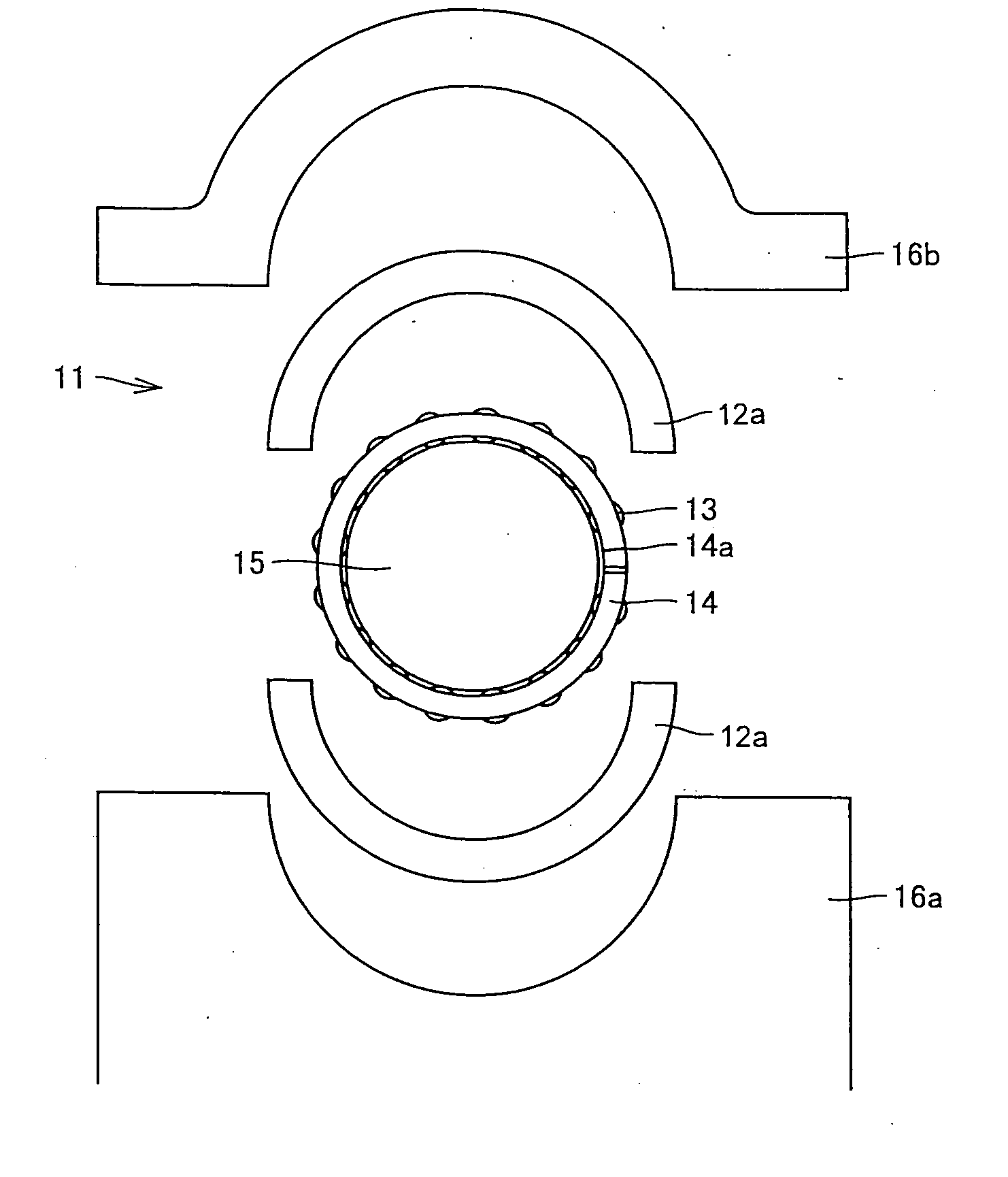
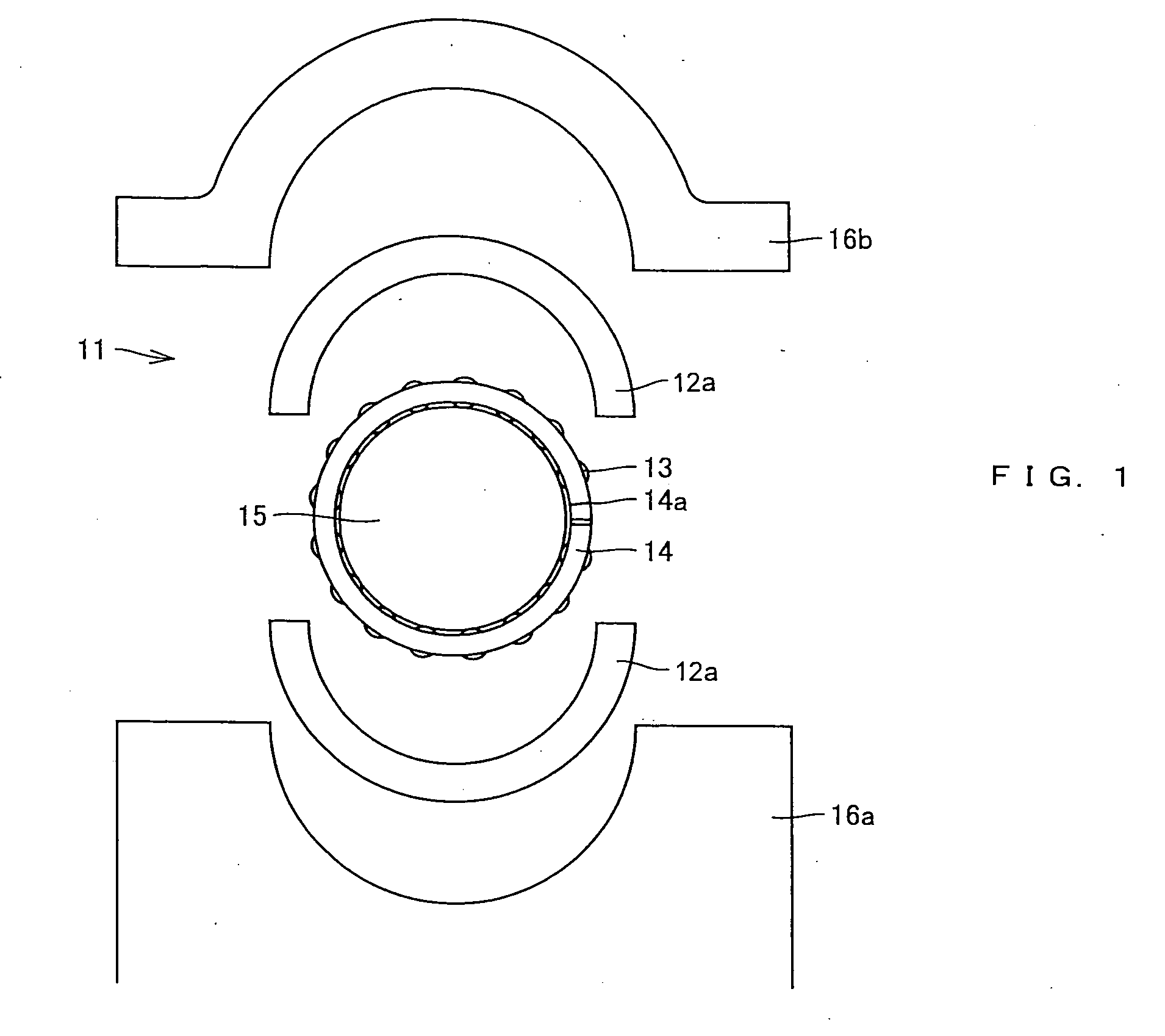
[0118] A crank shaft supporting structure according to one embodiment of the present invention will be described with reference to FIG. 1 hereinafter.

[0119] The crank shaft supporting structure shown in FIG. 1 comprises a crank shaft 15, a cylinder block 16a, a bearing cap 16b, and a needle roller bearing 11 arranged between the crank shaft 15 and the bearing cap 16b and supporting the crank shaft 15 rotatably.

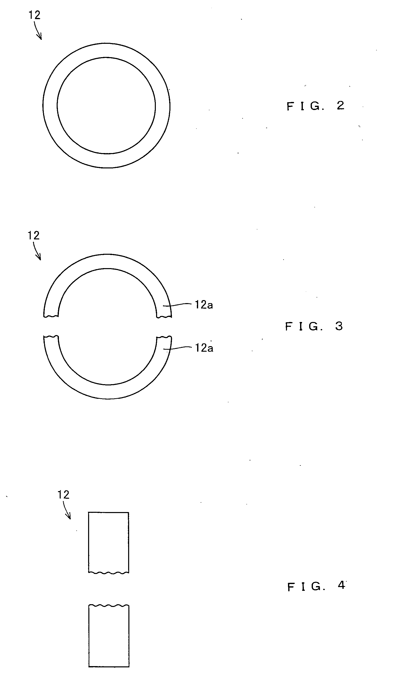
[0120] The needle roller bearing 11 comprises an outer ring 12 having a plurality of outer ring members 12a split by split lines extending in the axial direction of the bearing, a plurality of needle rollers arranged on the track surface of the outer ring 12 so that they can roll, and an integral retainer 14 having a cut part 14a extending in the axial direction on the circumference.

[0121] According to the needle roller bearing 11, since the needle roller 14 and the track surface are linearly in contact with each other, high load capacity and high rigidity can be provided f...


PUM


Abstract

A needle roller bearing comprises an outer ring having a plurality of outer ring members split by split lines extending in the axial direction of the bearing, and a plurality of needle rollers arranged on the track surface of the outer ring so that they can roll. The outer ring is split by a load applied to its end surface in the direction crossing the end surface.

Description

BACKGROUND OF THE INVENTION [0001] 1. Field of the Invention [0002] The present invention relates to a crank shaft supporting structure used in an engine of a car and the like. [0003] 2. Description of the Background Art [0004] As shown in FIG. 25, a crank shaft 101 comprises a shaft 102, a crank arm 103, a crank pin 104 for arranging a con-rod between the adjacent crank arms 103. As shown in FIGS. 26 and 27, the shaft 102 is rotatably supported by a sliding bearing 105. Since the sliding bearing 105 has high load capacity, it is suitable for use under a high load environment. Furthermore, a cylinder block 107 (referred to as an “engine block” also hereinafter) and a bearing cap 108 are mounted on the outside the sliding bearing 105. [0005] Referring to FIG. 27, since the sliding bearing 105 cannot support an axial load, a thrust washer 106 is arranged between the crank arm 103, and the engine block 107 and the bearing cap 108 in order to prevent the crank shaft 101 from moving in t...

Claims


Application Information

Patent Timeline
IPC IPC(8): F16C9/00
CPCF16C9/02F16C19/46F16C33/4694F16C33/516F16C33/543F16C33/60F16C2360/22
Inventor OISHI, SHINJINISHIKAWA, MAKOTOKATAYAMA, AKIHIKOTERADA, TAKANORISAKAI, TAKAAKIABE, KATSUFUMIOKAGAWA, MASAAKI
Owner NTN CORP
Why Eureka
Try Eureka